Basic Networking Technology
In this chapter, we will familiarize you with some basic TCP/IP networking terminology, technology, and tools. While knowing the material in this chapter won't automatically qualify you for a new career in network suystem administration, you will bemuch closer to your new career. If you would like to learn much more about this topic, see the excellent O'Reilly book by Craig Hunt titled TCP/IP Network Administration.
You may find that this chapter is a bit daunting when it delves into binary numbers, but we recommend that you read it once from end to end to get a sense of the issues. As we actually build home networks later in the book, we will be referring back to this information. Some of the harder concepts in this chapter will make much more sense when viewed in the context of a real example.
To Do
- Command table at the end of the chapter
- Make sure to add a troubleshooting tutorial someewhere (ping big packets)
- Check on the .0 convention - is this prohibited - or just avoided like the plague?
Starting with the Numbers
The Internet runs a networking protocol called "Internet Protocol" which is usually referred to as "IP". This protocol allows millions of computers to interoperate in a standard way using the large global Internet. For this to work, each computer connected directly to the Internet must have a unique number, much like your telephone has a telephone number. Not only must the numbers be unique, but the numbers must indicate "where" the computer is connected to the network.
Telephone numbers are a good analogy - for example, consider the following telephone number:
+ 41-22-76-74101
For those of you, not familiar with international phone numbers, the "41" indicates that this phone number is in Switzerland. The "22" indicates that the phone number is in the city of Geneva. Now imagine if you wanted to call that number from 517-694-0981 (517 = Michigan 694 = Holt, Michigan). When the local phone company in Holt, MI sees the international call, all it must do is look at the prefix of the number to know that this call is destined for Switzerland. But in Holt, Michigan, there is no need to understand the city code. As the telephone connection is set up, at some point it gets close enough to look beyond at the country code and look at the city code. And once in the city, the remaining numbers are used to find the area within the city and then the precise telephone location.
This concept that the farther that you are from a destination, the less detail you know is a very important one in IP and the Internet. About this point, you are probably thinking, "I have been on the Internet for years now and I never even knew that my computer had a unique number!". That would be because the numbers are assigned automatically for most dial-up connections. About the only time you might encounter the numbers would be when you were connected at work. And even then, if the numbers needed changing, a mystical creature called the "network adminstrator" would appear from the mist, change your numbers, and disappear back into the mist telling you never to change those numbers or some untold fate would befall you.
But as you become the network administrator for your home, you will need to know these numbers and know them well. But by the end of this chapter, you might actually think that the job of a network administrator might just be a little fun. Of course it is all fun until your family starts paging you when the connection is not working.... But I digress.
IP Addresses
Each computer which is directly connected to the Internet is assigned a unique address which includes information about where the computer is connected to the Internet. The addresses are 32-bit numbers which are generally displayed in the following form:
35.8.2.41
where each of the four numbers represents an 8-bit value from 0-255.
Connecting a Local Area Network to the Internet
While most of you have your home connection through a modem, it is simpler to learn about IP addresses in a local area network (LAN) configuration. Once we understand the configuration on a LAN, we will examine how the PPP/modem connection is configured.
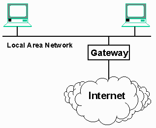 The IP protocol was designed to connect all the computers on a particular LAN segment to the Internet by attaching a single piece of equipment to the network. This equipment is called a "gateway" or "router", because it acts as a gateway between the computers on the local network and the Internet. Its purpose is to intelligently "route" data between the LAN and the Internet.
For a workstation to be properly configured to use the TCP/IP protocol to connect to the Internet it must be aware of the following information:
-
The workstation's own IP address
-
The IP address of the gateway to the rest of the Internet
-
The set of IP addresses which are are on the LAN (i.e. data to these systems does not have to pass through the gateway)
-
The IP addres of the Domain Name Server (DNS). This system maintains a list of human-readible domain names (www.ford.com) and the mapping of those names to IP addresses. This allows us to refer to a computer with an name that is easier to use. It also allows the owner of a system like www.ford.com to move the system, changing the IP address of the system while maintaining the same domain name.
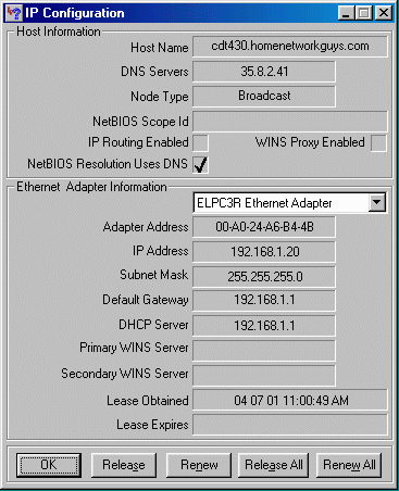 To look at an example, we will use the utility winipcfg which is available under Windows-95/98.
At the end of this chapter, there is a table showing the commands to use for other operating systems to perform the network diagnostic functions throughout this chapter.
Looking at the output for winipcfg, we quickly can pick out the workstation's IP address, the gateway address, and the Domain Name Server (DNS) address. The only field which is less-than-obvious is the Subnet Mask.
The Subnet Mask is used to answer the question as to which IP addresses are connected to the local area network and which addresses are connected to the Internet on the other side of the gateway. It would have been much simpler if the display looked like:
LAN Attached Addresses:
192.168.1.*
Using a wild-card would let us know that address which match the first three numbers are local, and any address where the first three numbers do not match must be on the other side of the gateway. In actuality, this is exactly what a subnet mask of 255.255.255.0 indicates. When the first three numbers match, the workstation is local, when they do not match, the packets must be routed through the gateway.
The following table gives some example subnet mask values and their impact:
Mask Value         Local addresses
255.255.255.0      When the first three numbers match
255.255.0.0        When the first two numbers match
255.0.0.0          When the first number matches
255.255.255.248    See below
You might actually make it quite a ways before you encountered a more complex subnet mask value such as 255.255.255.248, but this netmask is common when using a cable modem. It allows a total of 6 address on the local network. To understand this subnet mask value, we must delve a little deeper. And in the process we will learn why it is called "subnet mask" in the first place.
We mentioned above that IP adresses were 32-bit numbers commonly displayed in the "dotted" format (192.168.1.20) where each of the numbers represented eight bits was in the range of 0-255. The following table shows some numbers and their corresponding bit patterns:
Number     Bit Patterns
255        11111111
254        11111110
252        11111100
248        11111000
240        11110000
224        11100000
192        11000000
128        10000000
So a netmask of 255.255.224.0 would look as follows in bits:
11111111 11111111 11100000 00000000
The general pattern is that starting at the left, there is some number of one bits followed by the remainder of the bits being zero. The above might be called a "19-bit subnet mask" because the top 19 bits are ones followed by 13 bits of zero.
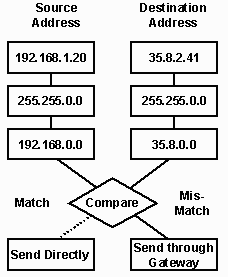 Subnet masks are used to compare the destination comptuter's IP address with our IP address. We only compare the positions where there are ones in the netmask. Here are
some address comparisons with a netmask of 255.255.0.0:
              Address         After Netmask
Source        192.168.1.20    192.168.0.0
Destination   35.8.2.41       35.8.0.0
  --> This is an Internet address and must
      be sent through the gateway

Source        192.168.1.20    192.168.0.0
Destination   192.168.200.7   192.168.0.0
  --> These is a local address and does not
      need to use a gateway
In addition to detemining which addresses are local and which addresses must be accessed through the gateway, the subnet mask also implicitly defines the maximum number of computers which can have unique IP addresses on a single local network. In an earlier example:
  IP Address:     192.168.1.20
  Subnet Mask:    255.255.255.0
The local area network can have addresses in the range of 0-255. The ".255" (all ones) address should never be used because it is a "broadcast address", and one of the addresses should be used for the gateway address (typically the ".1" address) so there are 253 possible workstation IP addresses for this network segment. The following is a table with netmasks and network sizes:
Netmasks		 Network Size
255.255.255.248    6 addresses
255.255.255.240    14 addresses
255.255.255.0      253 addresses
255.255.0.0        253*255 addresses
255.0.0.0          253*255*255 addresses
This may all seem much more complex than necessary, but if you are comfortable in base-2, it is not too hard to understand. There are a number of "subnet address calculators" on the Internet in the case that you encounter a subnet such as 255.255.255.248. Here is a common example worked out in complete detail:
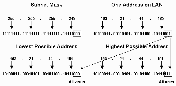
The netmask indicates which addresses are on the local network by indicating which bits must not change and which bits are allowed to change. Given that the top 29 bits of the netmask are ones, the only bits which can change and have the address still remain on the local network are the last three bits. Your ISP will give you the netmask value and at least one address on "your" network. This address might be the gateway address, a workstation address or both. But given any one address on the LAN, we can calculate the range of addresses which are local to the LAN. After converting the known address to base-2, we simply set the bottom three bits to all to zero to find the "lowest address" on the LAN and then set the bottom three bits all to one to find the "highest address" on the LAN. Remember that the "highest" address should never be used because it is broadcast address. As a result the range of addresses on this LAN is 163.21.44.184 - 163.21.44.190.
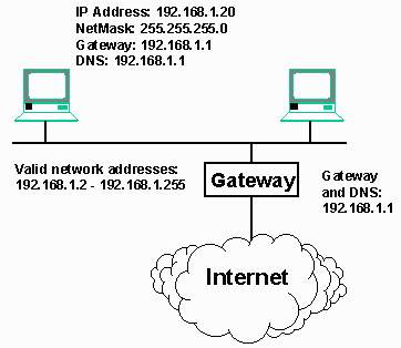 So, in our simple network example, we can label all of the elements in our network. In this example, the domain name server (DNS) address and the gateway are the same, but this does not have to be the case. The DNS server can be an address on the local network, or an address connected to the Internet. In this case, the gateway is acting as the DNS server in addition to being the gateway/router.
Having the gateway and DNS address the same is very common on home networks because both hardware and software gateways support both services. On a corporate LAN, these two numbers would almost certainly be different.
Managing IP Addresses
Now that we have an understanding of the three main addresses used to configure a workstation and place it both on the local area network and the Internet, it is time to take a look at how we manage these IP addresses. There are three basic ways that IP addresses are managed:

-
Automatically using Point-to-Point Protocol (PPP) - When a single computer (or home gateway) dials up an Internet Service Provider (ISP), part of the dial-up process assigns your connection an address from their network. Each time you dial-up, you may get a completely different address.
-
Manually - In a home network where multiple computers will be connected to the Internet, you can write all the addresses down in a simple text document or spreadsheet. You must enter the IP address and other onfiguration manually on every system connected in the house.
-
Automatically using the Dynamic Host Configuration protocol (DHCP) - This requires a system on the local area network to be configured to serve addresses. Each system on the network (other than the DHCP server) is configured to request their address while it is booting up and starting TCP/IP.
You can access the screen shown above for both your dialup "adapter" as well as the "Ethernet adapter". Windows will generally warn you strongly against using anything other than dynamic addresses on any dial-up adapter because PPP will override and of your fixed settings. On the LAN adapters however, you can choose a static address or a dynamic address via DHCP. But you should only chose dynamic if you know that there is a DHCP server avaialable.
DHCP Configuration
There are four typical ways to use a DHCP server:
-
You use a home gateway unit such as an Apple Airport, 3Com LanModem, or LinkSys unit. These units generally will perform DHCP, DNS, gateway routing, and Network Address Translation (see next chapter).
-
You use a software gateway such as WinRoute or Sygate. These programs generally perform the same functionality as the hardware units described above.
-
You have a cable modem or DSL with an Ethernet connection. Your ISP runs a DHCP server and will provide you with your configuration information on startup.
-
You run a Windows-2000 server or Linux server where you have explicitly configured a DHCP server.
 In any event, if you have a DHCP server, then the management of the IP addresses on the workstations attached to your network is quite simple. They all are set to obtain their addresses dynamically and the rest is up to the DHCP server.
When these computers boot up, they send out a special broadcast packet (Reverse Address Resolution Protocol or RARP) on the LAN which effectively asks the question, "What is my address information?". If there is a DHCP server running, the server responds with the proper IP address, netmask, gateway, and DNS server. These values are set for the workstation and used until the workstation is rebooted.
When the DHCP server gives a workstation an IP address, it is called a "lease" because the address is only good for a limited time which can range from hours to days. If you look at the output of the Windows utility winipcfg, you can see the address of the DHCP server which was used to configure this workstation and the expiration time on the "lease" for this configuration.
It is the workstation's responsiblity to "renew" their lease on the IP address sometime before the lease expires. If the lease is not renewed by the expiration time, the address is placed back into a pool of addresses to be given to the next computer which makes a request for an IP address. One advantage of this approach is that if a computer is rebooted before the lease expires, it will be given the same address by the DHCP server.
You can force the workstation to release its IP address lease using the Release button on winipcfg and you can renew the lease using the Renew button. It is not necessary to release the address before you renew it. Releasing and renewing your address is a good way to test that your DHCP server is actually working properly. If the DHCP server is not present and there is no response to the RARP request, you may get a garbage address when DHCP times out.
When a computer goes to sleep under Windows-98 and wakes back up, it re-obtains its IP address and network configuration using DHCP protocol. If the lease has not expired, it is given the same addres that it had before it went to sleep.
DHCP is very convienent because it allows any computer to be connected to the LAN without requiring any specific configuration. For example, a portable computer configured to use DHCP can be seamlessly moved between your office network and your home network. The DHCP server on each network provides the workstation with the right information it needs for each of the different networking environments.
It is possible for a network to handle both static and dynamic addresses at the same time. Because DHCP gives out addresses in a particular range, you can reserve a portion of your subnet for static addresses and another portion of the subnet for DHCP configured addresses. This way, you have the best of both worlds - you can assign fixed addresses to your home gateways and your servers, while using dynamic addreses for the user workstations and any portable computers that you might use.
In looking at the winipcfg output, we have covered nearly all of the fields in the screen. The fields in the top half of the output (Node Type, NetBIOS Scope, WINS Proxy, and NetBIOS Resolution) are all related to file sharing over the LAN and will not be covered here. The Adapter Address is the "serial number" of the LAN card. We will examine these "adapter addresses" next.
Ethernet Addresses
The Internet Protocol (IP) can operate across a wide range of local area networks including: Ethernet, Token-Ring, Fiber Distributed Data Interface (FDDI), Asynchronous Transfer Mode (ATM), and others. By far the most common local area network technology we will see in the home is the Ethernet network. So in this book, we will ignore all other LAN technologies and focus on Ethernet.
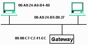 In the winipcfg output, we can see the adapter address for an Ethernet connection, this number is the serial number of the Ethernet card in the system.
These Ethernet card serial numbers are 48-bit numbers with the top 24 bits used to indicate a manufacturer identifier. The bottom 24 bits are the serial number of the card within the particular manufacturer. These addresses are typcally written as a series of six hexadecimal numbers:
00-A0-24-A6-B4-4B
These Eithernet addresses are used to move data across the local area network. Each packet must have a source and destination address to move across the network. An address of FF-FF-FF-FF-FF-FF (all ones) is used as a broadcast address, meaning that the packet is received by all of the workstations on the local area network.
The Internet Protocol (IP) and Ethernet work together. IP is used to move data acoss many different types of media, whereas Ethernet is used to move the IP data across a single local area network. For every workstation on Ethernet using IP, there is both an Ethernet address and an IP address. Each computer must maintain a table of the mapping from the IP addresses to Ethernet addresses. This table is called the ARP-table because the protocol used to discover new IP address is is called the Address Resolution Protocol (ARP). When a workstation wants to communicate with an IP address across the Ethernet, it sends out an Ethernet broadcast ARP request. Sincle all of the workstations on the LAN receive the ARP, they each check to see if they match the desired IP address - if so, they reply and the originating workstation updates their ARP table.
Once an entry is in the ARP table, when your workstations wants to send a packet to an IP address, it knows the correct Ethernet address to use. On most systems, there is a command to interact with your workstation's ARP table called arp. In Windows systems, simply type te command arp -a in a command window to dump the contents of the ARP table.
Point-to-Point Protocol Connections
PPP connections are both very simple and somewhat complex at the same time. Because PPP is so well integrated into Windows and Macintosh operating systems, all we really need to know is a phone number, account and password and the rest is magic. This section looks a little deeper into how PPP operates in terms of its network configuration.
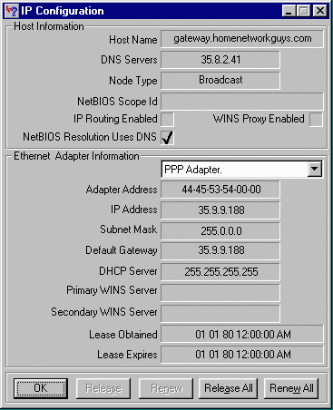 When PPP dials the modem, for the first few seconds, there is a bunch of housekeeping which must be done. First the connection must be authenticated. Once the authentication is done, the ISP tells your workstation which address values your workstation is to use.
When we look at the winipcfg output for the PPP Adapter once the connection is up, we can examine the settings which your ISP has assigned to your workstation. The IP address and subnet mask are addresses which make sense on the ISP's local area network. These values are only used for this particular dial-up session.
The Adapter Address is not really an Ethernet address in this case - it is just a way for Windows to keep track of multiple network connections.
Looking at these particular values, addresses with a 35.*.*.* value will be sent out on the "local network" while other addresses will be sent to the gateway address.
How IP Works
While you will probably never run a nationwide IP backbone, it can sometimes help to understand how packets move across the country and around the world. A simple tool to send a single packet across the IP network is called ping. This can be used to test basic connectivity between two systems. C:\WINDOWS>ping 137.138.28.228
Pinging 137.138.28.228 with 32 bytes of data:
Reply from 137.138.28.228: bytes=32 time=280ms TTL=115
Reply from 137.138.28.228: bytes=32 time=310ms TTL=115
Request timed out.
Reply from 137.138.28.228: bytes=32 time=279ms TTL=115
Ping statistics for 137.138.28.228:
Packets: Sent = 4, Received = 3, Lost = 1 (25% loss),
Approximate round trip times in milli-seconds:
Minimum = 279ms, Maximum = 310ms, Average = 217ms
C:\WINDOWS>
For each packet, ping tracks the round-trip time, and reports the Time to Live (TTL) value which we will examine more closely in a moment.
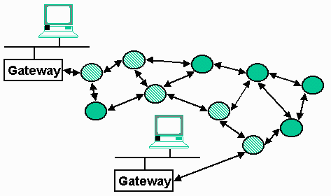 If we expand the "Internet cloud" a bit, we see the Internet made up as a series of network routers connected using various media ranging from leased telephone connections to dedicated fiber optic connections. Each packet finds a path from the source to the destination depending on the performance of each connection and the load on each of the routers. Two packets sent one right after another may take completely different routes through the network although this is not typical.
We can see the route a packet actually takes through the network using
the tracert command:
C:\WINDOWS>tracert 137.138.28.228

Tracing route to webr.cern.ch [137.138.28.228]
over a maximum of 30 hops:

  1     2 ms     1 ms     1 ms  COMPAQ_5630 [192.168.1.1]
  2   152 ms   157 ms   144 ms  ppp-gw-9-188.net.msu.edu [35.9.9.188]
  3   162 ms   153 ms   176 ms  cc-rtr-ve10.net.msu.edu [35.9.10.1]
  4   159 ms   157 ms   151 ms  g2-0-0.msu4.mich.net [35.9.82.98]
  5   154 ms   155 ms   152 ms  atm1-0x18.michnet8.mich.net [198.108.23.30]
  6   154 ms   155 ms   154 ms  s2-0-3c0x10.mtu.mich.net [198.108.23.237]
  7   165 ms   170 ms   161 ms  abilene-clev.mich.net [192.122.183.10]
  8   169 ms   169 ms   169 ms  ipls-clev.abilene.ucaid.edu [198.32.8.25]
  9   316 ms   204 ms   229 ms  cern-abilene.cern.ch [192.65.184.190]
 10   335 ms   288 ms   300 ms  cernh9-pos100.cern.ch [192.65.184.34]
 11     *      320 ms   343 ms  cgate2.cern.ch [192.65.185.1]
 12   290 ms   291 ms   283 ms  cgate1-dmz.cern.ch [192.65.184.65]
 13   355 ms   373 ms   284 ms  b513-b-rca86-1-gb0.cern.ch [128.141.211.1]
 14   327 ms   319 ms   305 ms  b513-c-rca86-1-bb1.cern.ch [194.12.131.6]
 15   327 ms   319 ms   287 ms  webr.cern.ch [137.138.28.228]

Trace complete.

C:\WINDOWS>
From this output, you can see that there are a total of 15 hops from the source to the destination.
Finding the path through the Internet works by placing special values in the
Time-To-Live (TTL) field. The TTL field is normally set to 128 in every packet. Each time a packet crosses a router or is delayed for a second inside of a router, this number is decreased by one. Once the TTL value goes to zero, the packet is not forwarded any further and an error message is sent back to the sending host. The original purpose of this field is to keep data from being forwarded forever when there is no path from the source to the destination.
To learn the path,
tracert first sends out a packet with a TTL of one, and then gets the error message returned after the first hop. Then a packet is sent out with a TTL of two, and the error message is returned. This pattern continues until tracert has effectively found the path from the source to the destination.
This command can be quite useful in debugging network connectivity - if a packet is getting part of the way from the source to the destination, a ping or other command will simply fail. The tracert command will show how far the packet is getting before it gets lost. This command also allows you to track the packet as it passes through any of your local gateways and onto the Internet.
Transmission Control Protocol (TCP)
In each of the above examples, we see packets which were lost. This is a critical aspect of the design of the IP protocol. Part of the reason that the Internet has effectively scaled to millions of hosts is the fact that IP allows packets to be lost. When a system sends a packet across the Internet, the Internet does not guarantee its delivery. Packets can be lost for any number of reasons: A link is too busy, a router is rebooted, the routing path is changed at just the wrong moment, or a leased line has a failure. If any of these happen, the Internet simply loses the packets and expects that the source and destination computers to cope with the loss.
However, usually we want to move data across the Internet and know that it actually arrived in one piece. Reliable delivery of data from a source to a destination is accomplished by the Trasnmission Control Protocol (TCP). TCP operates on top of IP and adds value to the IP protocol. Typically when we don't want to get into detail, we refer to TCP and IP together as TCP/IP.
The TCP protocol is very complex and robust, but its overall operation is quite simple. When one host sends data to another over TCP, the source host retains the data in its memory until it has received a positive acknowlegement from the destination system. If no acknowledgement has been received after a period of time, the data is re-sent. If the data has been resent too many times, the connection is terminated.
In addition to buffering and resending data, TCP also make sure data arrives in order. This is done by storing any out of order information on the the destination system until all the data has arrived. Then the data is put back into order and sent to the application.
When a web browser retrieves data using the Hypertext Transport Protocol (HTTP) or File Transfer protocol (FTP), the data is actually sent across the network using TCP and IP. FTP and HTTP are examples of application level protocols which make use of the TCP reliable connections.
A good analogy for IP is the postal system. You can place a bunch of letters in the mailbox addressed to the same location. Some time later, the letters are delivered at the destination in any order with one or more of the letters getting lost (once in a great while). TCP is much more like the telephone system - you make a connection and it just works smoothly until you are done. Sound goes in and comes out in the same order. Nothing is lost (not counting cell phones), and about the only thing that goes wrong is that the connection is terminated if there is a problem.
A View from a Gateway
So far, we have concentrated on the view from a workstation in terms of how to get our data to destination hosts on the Internet. Now we will take a brief look at a gateway (also called a router).
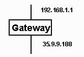 A gateway is a system which has more than one network connection and can forward data among their network connections. The simplest case is a gateway with two connections. Each connection has an IP address which makes sense on the local area network to which it is connected and is properly configured with a netmask and a gateway for that network.
The gateway must know which subnets are available on which interface. The table which contains this information is called the route table. This table can be dumped using the netstat command under Windows:
C:\WINDOWS>netstat -rn

Active Routes:

  Network Address          Netmask  Gateway Address        Interface  Metric
          0.0.0.0          0.0.0.0       35.9.9.188       35.9.9.188       1  (1)
         35.0.0.0        255.0.0.0       35.9.9.188       35.9.9.188       1  (2)
       35.9.9.188  255.255.255.255        127.0.0.1        127.0.0.1       1  (3)
        127.0.0.0        255.0.0.0        127.0.0.1        127.0.0.1       1  (4)
      192.168.1.0    255.255.255.0      192.168.1.1      192.168.1.1       2  (5)
      192.168.1.1  255.255.255.255        127.0.0.1        127.0.0.1       1  (6)
This table looks somewhat daunting, but with all the knowlege that we now have in this chapter, we can work our way through it. When a packet arrives on any network interface, the table is read from the bottom to the top. Each packet is destined for one of three interfaces: the dial-up modem connection (35.9.9.188), the local area network connection (192.168.1.1), or the gateway itself (127.0.0.1). The network address and netmask are used to see if the destination address matches this particular "row" in the table. If there is a match between the destination address and the network address after the netmask is applied
to both, then the packet is send out the specified interface.
Working from the bottom to the top the rows have the following meaning:
-
Row 6 means that if the destination matches 192.168.1.1 exactly, the packet is destined for this computer (the gateway)
-
Row 5 means that any packets with a destination address of the form 192.168.1.* are to be sent out to the local area network using the Ethernet interface.
-
Row 4 says that any address 127.*.*.* is local to this computer.
-
Row 3 says that if the destination is 35.9.9.188, then it is destined for this computer. Remember that this computer has two network interfaces.
-
Row 2 says that any address of the form 35.*.*.* is sent out the PPP connection.
-
Row 1 says that if none of the other rows have matched the destination address (for example if the destination was 62.145.22.33), send the packet out the PPP connection.
Several rows were removed from the table to keep it simple. When you print this table out on your computer, you may find some rows with network addresses starting with 224 or network addresses containing 255. The 224 addresses are for multicast traffic and the 255 addresses are for IP broadcast traffic.
This table is easily extended for gateways with more than two interfaces. Essentially the table lists all of the subnets which are to be sent to which interface, and then in the first row indicates where to send packets which don't match any of the rules.
Conclusion
You can go quite a long way in home networking without having to know every concept presented in this chapter. But it does help when diagnosing a problem to be able to read the outputs of the tools which allow you to explore the network configuration.
The Internet is successful in a large part due to the clever design of the TCP and IP protocols.
-
Each computer needs a very small amount of information to connect to the network.
-
The IP protocol does not have to guarantee reliability for data. This allows the Internet to move data quickly and cheaply using a "best effort" model.
-
The TCP protocol adds sequencing and retransmission on top of IP so that data can be moved reliably between applications.
Once your computer network is properly setup, it will run with little or no maintenance and you will begin to forget that you ever needed the information in this chapter. Most of the routine aspects of network configuration can be completely automated with the proper hardware or software. But when things break down, that is when you will come back to this chapter and read it very carefully.
 The IP protocol was designed to connect all the computers on a particular LAN segment to the Internet by attaching a single piece of equipment to the network. This equipment is called a "gateway" or "router", because it acts as a gateway between the computers on the local network and the Internet. Its purpose is to intelligently "route" data between the LAN and the Internet.
 To look at an example, we will use the utility winipcfg which is available under Windows-95/98.
At the end of this chapter, there is a table showing the commands to use for other operating systems to perform the network diagnostic functions throughout this chapter.
Looking at the output for winipcfg, we quickly can pick out the workstation's IP address, the gateway address, and the Domain Name Server (DNS) address. The only field which is less-than-obvious is the Subnet Mask.
 Subnet masks are used to compare the destination comptuter's IP address with our IP address. We only compare the positions where there are ones in the netmask. Here are
some address comparisons with a netmask of 255.255.0.0:

 So, in our simple network example, we can label all of the elements in our network. In this example, the domain name server (DNS) address and the gateway are the same, but this does not have to be the case. The DNS server can be an address on the local network, or an address connected to the Internet. In this case, the gateway is acting as the DNS server in addition to being the gateway/router.

 In the winipcfg output, we can see the adapter address for an Ethernet connection, this number is the serial number of the Ethernet card in the system.
These Ethernet card serial numbers are 48-bit numbers with the top 24 bits used to indicate a manufacturer identifier. The bottom 24 bits are the serial number of the card within the particular manufacturer. These addresses are typcally written as a series of six hexadecimal numbers:
 When PPP dials the modem, for the first few seconds, there is a bunch of housekeeping which must be done. First the connection must be authenticated. Once the authentication is done, the ISP tells your workstation which address values your workstation is to use.
 If we expand the "Internet cloud" a bit, we see the Internet made up as a series of network routers connected using various media ranging from leased telephone connections to dedicated fiber optic connections. Each packet finds a path from the source to the destination depending on the performance of each connection and the load on each of the routers. Two packets sent one right after another may take completely different routes through the network although this is not typical.
 A gateway is a system which has more than one network connection and can forward data among their network connections. The simplest case is a gateway with two connections. Each connection has an IP address which makes sense on the local area network to which it is connected and is properly configured with a netmask and a gateway for that network.