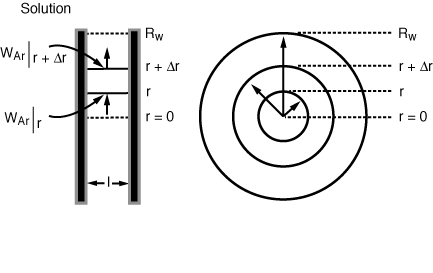

The shell balance on the reactant diffusing between two wafers separated by a distance l shown in Figure CDE12-9.1 gives

 is the rate of generation of species A per unit
wafer surface area. The factor of 2 appears in the generation term because there
are two wafer surfaces exposed in each differential volume element. Dividing by
 , taking
the limit as
 approaches zero, and then rearranging gives


Diffusion between
the wafers

Figure 12-9-1


Diffusion with
reaction between
wafers


(CDE12-9.5)
(CDE12-9.6)
(CDE12-9.7)
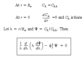
 The boundary conditions are


 o
is a modified Bessel function of the first
kind of order zero and K o is a modified Bessel function of the
second kind of order zero. The second boundary condition requires
  to be finite at
  = 0. Therefore, B must be
zero because K o (0)
=
 .
Using the first boundary condition, we get
 ; then
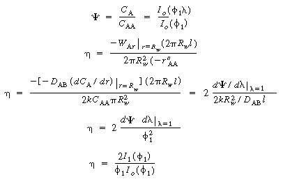
  . The concentration profile in the space between
the wafers is

(CDE12-9.9)
(CDE12-8.10)
(CDE12-9.11)
(CDE12-9.12)

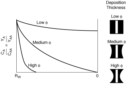
Figure CD12-9-2
Radial concentration profile