![]()
|
|
Type 10 Home Problem -- Solution
Problems that develop life-long learning skills.
After reading the bubble column review by Y. T. Shah et al. [AIChE J., 28, 353 (1982)], we notice that there are two ways to attack this problem:
#1: Graphical Approach.
Use Figure 2.3 to approximate a superficial velocity (uG)
that will result in a conversion of 99.9%. Then size the reactor accordingly.
#2: Mole Transfer Approach.
Use Table 2.1 (find eG) and Table 4-a.2
(to find kLa). Then calculate the moles that must be transferred and the
volume required for that transfer.
#1 Graphical Approach
On page 357 of the article by Shah, there is a plot of carbon dioxide conversion versus initial superficial gas velocity (uGo). The results do vary with the height of the column. Using this graph, we will size a tall reactor (HC = 2.36 m) and a short reactor (HC = 0.41 m).
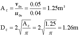
For the 2.36 m tall reactor, we see that the conversion approaches 100% at a superficial velocity (uGo) of about 0.04 m/s. This velocity is within the bubbly flow range. (The limit is usually ~ 0.05 m/s.) Knowing the volumetric gas flow rate (vGo) and the required superficial velocity of our system, we calculate the diameter of our column:
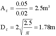
A conversion of 99.9% in a 0.41 m tall column will require a superficial gas velocity of about 0.02 m/s. Once again, we calculate our diameter:
A comparison of the tall and short columns:
|
Column |
Diameter |
Column |
Volume |
|
2.35 m |
1.26m |
1.25 m2 |
2.95 m3 |
|
0.41 m |
1.78m |
2.5 m2 |
1.03 m3 |
The conclusion that can be drawn from this data is that shorter columns are more efficient (on a per volume basis) in stripping carbon dioxide from the flue gas.
#2 Mole Transfer Approach
Our first step is to select our correlations for gas hold-up (eG) and mole transfer (kLa). We have chosen the following correlations from Akita and Yoshida (1973), because they are valid for carbon dioxide and water systems at relatively large column heights and diameters:

The driving force for this liquid phase transfer is the difference between the equilibrium concentration of carbon dioxide (CCO2*) and the actual liquid phase concentration of carbon dioxide (CCO2), which we will assume is zero (the sodium hydroxide instantly neutralizes the aqueous carbon dioxide). The rate of mole transfer per reactor volume can be written as:

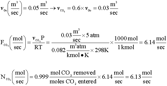
Our next step is to determine the rate of mole transfer that is needed to remove 99.9% of the carbon dioxide in the feed gas. We will assume that carbon dioxide is an ideal gas under the conditions of our column.
In order to calculate the mole transfer coefficient (kLa), we will need to find the following properties of our fluids:

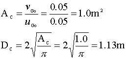
We will set our initial superficial velocity at the bubbly flow limit (uGo = 0.05 m/sec) and calculate the area and diameter of our column:
For the gas phase hold-up equation, we will set C = 0.2 and assume that the superficial velocity (uG) is approximately the average of the entering and exiting velocities (uG = 0.035 m/s). Using an equation solver, we get: eG = 0.055
Next, we solve for our mole transfer rate constant:
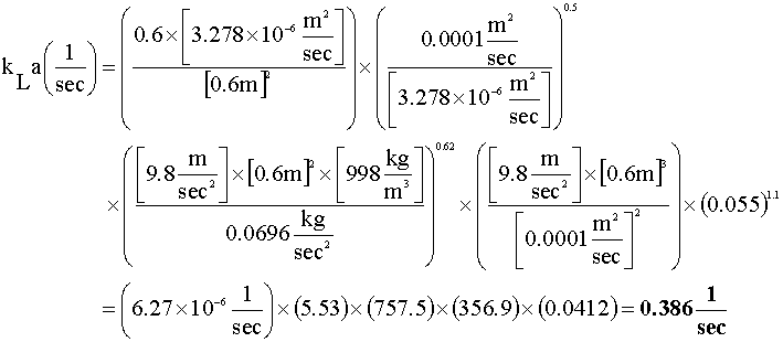
Going back to the driving force equation, when we solve for the reactor volume (V), we get:
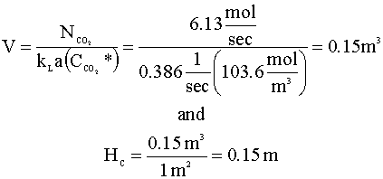
The dimensions of our bubble column are: DC = 1.13 m and HC = 0.15 m
The mole transfer correlation predicts that we will need a much smaller column than we would have predicted from the graphical approach.
Compare with Graphical Approach Results
Our results with the mole transfer approach are not the same as the graphical approach results, and this is probably due to some different assumptions we made in using the mole transfer approach:
Sparger Types
Two popular sparger types are perforated plates and porous spargers. We would choose the porous spargers, because they release bubbles with smaller diameters. As the bubble size decreases, the superficial velocity for bubbly flow increases and subsequently, the mole transfer rate increases.
![]() Back to Homogeneous Example 10
Back to Homogeneous Example 10
CRE Thoughts Ten Types Homogeneous Example 10