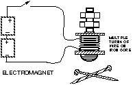
Wrap a coil, comprising many turns of enameled wire wrapped around a large, iron bolt.

Today we will use the coil to form an electromagnetic relay, an electrically-controlled switch, that has a variety of applications.
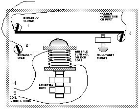
We denote the normally closed and normally open terminals as #1 and #2 ("Normally" means the status of the switch contact when no current is in the coil). The adjustment screw enables one to control the sensitivity of the relay to various levels of current.
 |  |
| Drawing | Schematic |
Here (above) we see a pictorial view of the relay and also an equivalent schematic diagram.
The simple circuit #1 feeds the relay coil, via a control switch, directly from the a 6V lantern battery:
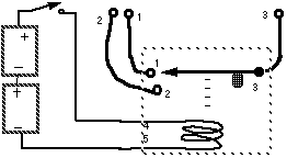
The adjustment screw is to be set so that the relay closes reliably when the current is fed to the coil.
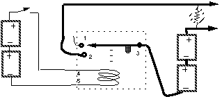
Build circuit #2 shown just below and explore its properties. Note that one battery drives the primary relay coil, while the other battery powers a light, in a circuit which is completely unconnected with the relay coil.
The next circuit (Circuit #3) is one in which the coil current itself goes through the relay contacts. Describe the behavior of this circuit. Does it have any utility? How would the circuit behave if you connected the coil (terminal 4) to terminal 2 of the relay?
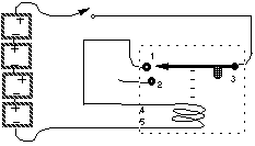
Make a sketch (a rough graph) of the current, when the relay is buzzing.
Use the hand-held oscilloscope to picture the voltage variation across the buzzer switch (points 1 and 3). Capture your picture with the hold button. Study and discuss your oscilloscope screen and copy the graph to your notebook for later reference.