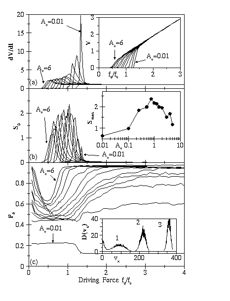

(a): dV/dI curves for vortex-vortex interactions
(right to left) A_v = 0.01, 0.1, 0.25, 0.5, 0.75, 1, 1.5, 2, 3, 4, 5, 6.
The peak in dV/dI increases in magnitude with decreasing A_v.
Inset to (a): Voltage-current V(I) curves for the A_v values listed above.
The depinning transition shifts to higher driving
currents f_d and becomes more abrupt as A_v decreases.
(b): Voltage noise power S_0 versus f_d for the A_v
values listed above. In each case the noise power peaks
during the plastic flow regime. Inset to (b): Maximum noise power
S_{max} as a function of A_v. The peak value of S_{max}
corresponds to A_v \approx 0.75, the same A_v at which
the system crosses between smectic and coupled channel behavior at high drives.
(c): Fraction of six-fold coordinated vortices P_6 as a function
of f_d for values of A_v listed above.
At zero drive and strong VL coupling, P_6 \sim 1 since the VL is field-cooled.
The lowest value of P_6 at each A_v corresponds exactly to the
peak in dV/dI. The VL eventually reorders to P_6 \sim 1 only when A_v \geq 1.
For A_v \leq 0.75, P_6 saturates at a value below 1.
Inset to (c): Velocity distribution functions D(v_x) for
(1) plastic, (2) smectic, and (3) coupled channel phases.
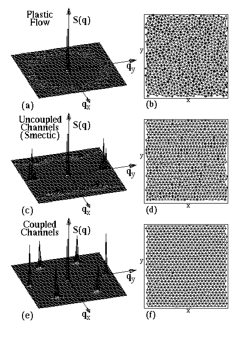
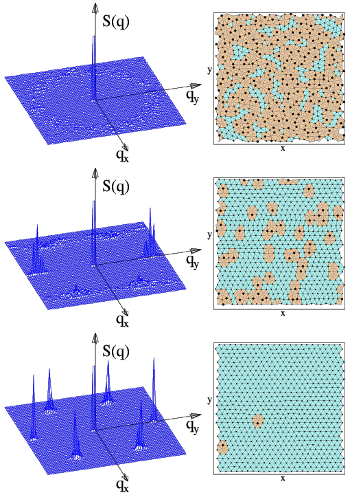
Structure factor S(q) (a,c,e) and Delaunay triangulations (b,d,f) of the VL for: (a,b) A_v = 1.5, f_d = 1.12 f_0, in the plastic flow regime. S(q) is liquid-like, and the VL is filled with defects (marked with circles). (c,d) A_v = 0.5, f_d = 3.04 f_0, in the uncoupled channel regime. S(q) has smectic peaks, and the defects in the VL are oriented transverse to the x-direction driving force. (e,f) A_v = 4, f_d = 3.04 f_0, in the coupled channel regime. S(q) has slightly anisotropic crystalline-like peaks, and the VL contains almost no defects.
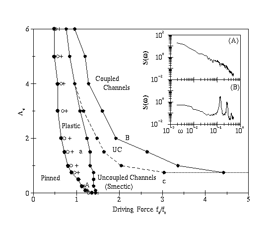
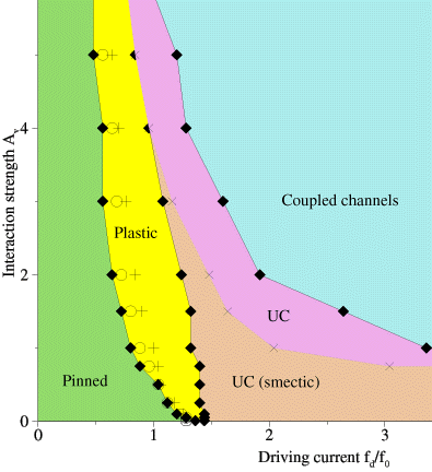
Dynamic phase diagram for different driving currents f_d and vortex-vortex interaction strengths A_v. At very low drives, the VL is pinned. In the plastic flow phase, we observe peaks in dV/dI (crosses) as well as peaks in the voltage noise power S_0 (circles). When A_v \leq 0.75, the VL flows in uncoupled channels for all high driving currents. For larger A_v, the VL passes through a transition region (UC) in which the channels progressively couple, until reaching a reordered state at high drives. A: Typical voltage noise spectrum S(\omega) \sim 1 / \omega observed near S_{max} for A_v = 0.1. B: Washboard frequency observed in the coupled channel regime for A_v = 2. The magnitude of the narrow band signal decreases in samples larger than the 36 \lambda \times 36 \lambda sample shown here. The letters A,B refer to inset plots shown here; a,c refer to the plots shown in Fig. 2(a) and 2(b).
Postcript Figures are available here (some in color, and some unpublished yet):
