Finite Element Method

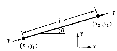
Fig. 1. A strait line element
Fig. 1 shows one element, with two nodes at the positions ( x 1 , y 1 ) and ( x 2 , y 2 ). The element has length 1 and slope ![]() , which relate to the nodal positions by the expression l*sin
, which relate to the nodal positions by the expression l*sin ![]() = y 2 -y 1 and l*cos
= y 2 -y 1 and l*cos ![]() = x 2 -x 1 . We specify a point on the element by its distance from the mid-point of the element, s . When the two nodes change their positions by
= x 2 -x 1 . We specify a point on the element by its distance from the mid-point of the element, s . When the two nodes change their positions by ![]() and
and ![]() , the element become straightened, elongated, translated, or rotated, according to the nodal position changes. Consequently, the element moves in the normal direction by distance
, the element become straightened, elongated, translated, or rotated, according to the nodal position changes. Consequently, the element moves in the normal direction by distance
![]() , (3)
, (3)
with the linear interpolation coefficients being
![]()
![]() . (4)
. (4)
Also for velocity,
![]() (5)
(5)
However, for flux,
![]() , (6)
, (6)
where J 1 , J 2 and J m , are the fluxes at the two nodes and the mid-point of the element, respectively, we used the quadratic interpolation coefficients,
 (7)
(7)
Writing the position and mass displacement in a column matrix ![]() and the velocity and mass flux in a column matrix q'.
and the velocity and mass flux in a column matrix q'.
![]() (8)
(8)
![]() (9)
(9)
We can write the integral Eq. 1 as
![]() , (10)
, (10)
where
 (11)
(11)
where we have used the shorthand notation ![]() ,
, ![]() ,
, ![]() .
.
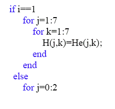
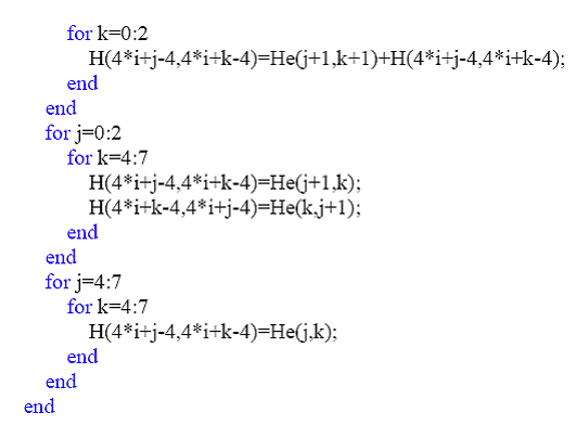
Since we need velocities for more than one element, we have to generate global H matrix, which is diagonal and includes matrix for each element. And it also has overlapped part for the same node of two adjacent elements. Here is the part of MATLAB code for global matrix.


The equation (2) can be express in term of force on the element
![]() (12)
(12)
where
 (13)
(13)
Equating Eq. 10 and Eq. 12 yields
![]() (14)
(14)
This equation is a set of linear algebraic equation for the generalized velocities. We use Matlab to solve for the velocity matrix. Note that taking an inverse of H is not possible since H is close to being a singular matrix. One way of suppressing the singularity is to add a small mass to the diagonal term of H matrix. In our program we use the command “psudoinverse”, which also suppresses the singularity.
Once solved, the nodal velocities can be used to update the nodal positions. Here we use Euler method for time evolution
![]() , (15)
, (15)
where x n is the current position and x n+1 is the new position. The accuracy of this method depends on the magnitude of time step. Since Euler method is an explicit method, the magnitude of time step has to be small compared with the magnitude of l . In our simulation we have dt/l =0.1.
----------------------------------------------------------------------------------
All formulation in this page refers to Ref. 4
[4] B. Sun, Z. Suo, and W. Yang, Acta Materialia 45 , 1907 (1997).