(CD12-3.55)
(CD12-3.56)
|
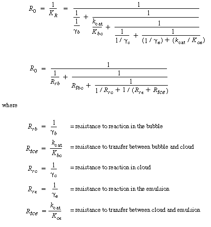
As engineers, it is important to deduce how a bed will operate if one were to change operating conditions such as gas flow rate and catalyst particle size. To give some general guidelines as to how changes will affect bed behavior, we consider the two limiting circumstances of reaction control and transport control. In the Kunii-Levenspiel bubbling-bed model, reaction occurs within the three phases of the bed, and material is continuously transferred between the phases. Two limiting situations thus arise. In one, the interphase transport is relatively fast and transport equilibrium is maintained, causing the system performance to be controlled by the rate of reaction. In the other, the reaction rate is relatively fast and the performance is controlled by interphase transport between the bubbles, clouds, and emulsions. It will be shown that the ammonia oxidation example used above is essentially a reaction-limited system. The overall reaction rate in the bed is proportional to K R , so the reciprocal of K R can be viewed as an overall resistance to the reaction. The different terms and groups on the right-hand side of Equation (CD12-3.49) can be viewed as individual resistances which can be arranged in series or parallel to give the overall resistance. |
 |
(CD12-3.55) (CD12-3.56) |
|
Example CD12-5 |
||||||
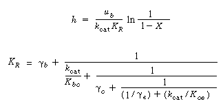
Slow ReactionIn addition to the obvious way of increasing the temperature to increase the conversion, and perhaps some unwanted side reactions, there are other ways that the conversion may be increased when the reaction is slow. From Equation (CD12-3.31) we know that the conversion depends on h, k cat , u b , and K R . We first determine K R under this situation. For a slow reaction, k cat is small compared to K bc and K ce , so that resistance to transport is essentially zero, that is, |
||||||
|
|
(CD12-3.58) |
|||||
and |
||||||
|
|
(CD12-3.59) |
|||||
then |
||||||
|
|
(CD12-3.60) |
|||||
Using Equation (CD12-3.41) to substitute for |
||||||
|
|
(CD12-3.61) |
|||||
Neglecting |
||||||
|
|
(CD12-3.62) |
|||||
Consequently, we see that K R can be increased by decreasing |
||||||
|
|
||||||
or about 11% higher than the value obtained by the more elaborate calculations, which included the transport. This would predict a conversion of 21.4%, very close to the 20% given by the method that includes the transport limitations. Thus the ammonia oxidation system of Massimilla and Johnstone is essentially a reaction-limited system. The conversion and catalyst weight are related by |
||||||
|
|
(CD12-3.63) |
|||||
Substituting for K R yields |
||||||
|
|
(CD12-3.64) |
|||||
Recalling Equation (CD12-3.23), we have |
||||||
 |
(CD12-3.23) |
|||||
In most instances u b is significantly greater than |
||||||
(CD12-3.65) |
||||||
Combining Equations (CD12-3.64) and (CD12-3.65) gives |
||||||
|
|
(CD12-3.66) |
||||
|
Therefore, one observes that to reduce the catalyst weight for a specified conversion, u 0
and |
|||||
Example CD12-6 |
||||||
Rapid ReactionTo analyze this limiting situation, we shall assume that the particles are sufficiently small so that the effectiveness factor is essentially 1 and that the rate of transfer from the bulk fluid to the individual catalyst particles is rapid compared with the rate of transfer between the fluidization phases. For the case of rapid reaction |
||||||
Using these approximations in the equation for K R , which is |
||||||
 |
||||||
one observes that the first term to be neglected is |
||||||
 |
||||||
Then neglecting the reciprocal of g e with respect to k cat /Kcb , K R becomes |
||||||
|
|
(CD12-3.67) |
|||||
There are two situations one can analyze here: |
||||||
 |
||||||
Situation 1 will be analyzed in the text; the analysis of situation 2 is left as an exercise. |
||||||
(CD12-3.68) |
||||||
The catalyst weight is given by combining Equations (CD12-3.54) and (CD12-3.68): |
||||||
(CD12-3.69) |
||||||
Neglecting |
||||||
|
|
(CD12-3.70) |
||||
On observing that the equation for Kbc , Equation (CD12-3.30), is the sum of two terms, A 0 and B 0 , |
||||||
 |
(CD12-3.30) |
|||||
one finds that the problem can be further divided.
|
||||||
Case A is considered here; case B is left as an exercise. For case A,
|
(CD12-3.71) |
|||||
Then |
||||||
 |
(CD12-3.72) |
|||||
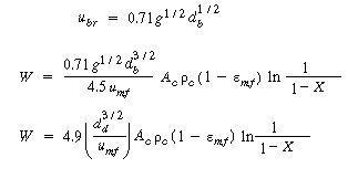
Recalling the equation for u b and neglecting other terms in the equation with respect to the velocity of rise of a single bubble, |
||||||
 |
||||||
and |
||||||
 |
(CD12-3.73) |
|||||
The average bubble diameter is a function of the tower diameter (thus the tower cross-sectional area Ac ), height, uo , and umf. As a first approximation, we assume that the average bubble diameter is some fraction (say, 0.75) of the maximum bubble diameter: |
||||||
(CD12-3.74) |
||||||
Then from Equation (CD12-38) we have |
||||||
(CD12-3.75) |
||||||
which is substituted into Equation (CD12-96) to give |
||||||
|
|
(CD12-3.76) |
||||
Example CD12-7 |
||||||
SUMMARY |
||
1. Minimum fluidization velocity:
|
(S12-1) |
|
2. Porosity at minimum fluidization:
|
(S12-2) |
|
or
|
(S12-3) |
|
3. Bubble size:
|
(S12-4) |
|
where |
||
(S12-5) |
||
For porous plates:
|
(S12-6) |
|
4. Velocity of bubble rise: |
||
(S12-7) |
||
5. Bed height÷conversion in first-order reaction: |
||
 |
(S12-8) (S12-9) |
|
6. Mass transfer parameters: |
||
a. Between the bubble and the cloud:
b. Between the cloud and the emulsion:
|
(S12-10) (S12-11) |
|
7. Reaction-rate parameters:
|
(S12-12) (S12-13) (S12-14) (S12-15) (S12-16) |
|
where |
||
|
|
||
Supplementary Reading
|