|
Transport from gas to single
|
|
|

|
(CD12-3.26) |
| |
|
|
|
| |
|
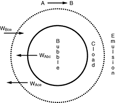 Figure CD12-3.5
Transfer between bubble, cloud, and emulsion.
|
|
| |
|
|
|
| |
|
Mass transfer coefficients obtained from these relationships may then be combined with mass transfer among the various phases in the fluidized bed to yield the overall behavior with regard to the transport of mass. Owing to the small particle sizes and high surface area per volume of solids used in fluidized beds, the mass transfer from the gas to the solid surface is usually quite rapid, and consequently, it seldom limits the reaction. |
|
| |
|
|
|
| |
|
Mass Transfer between the Fluidized-Bed Phases
For gas interchange between the bubble and the cloud, Kunii and Levenspiel 22 defined the mass transfer coefficient K bc(s-1) in the following manner: |
|
| |
|
|
|
| |
|

|
(CD12-3.27) |
| |
|
|
|
| |
|
|
|
| |
|
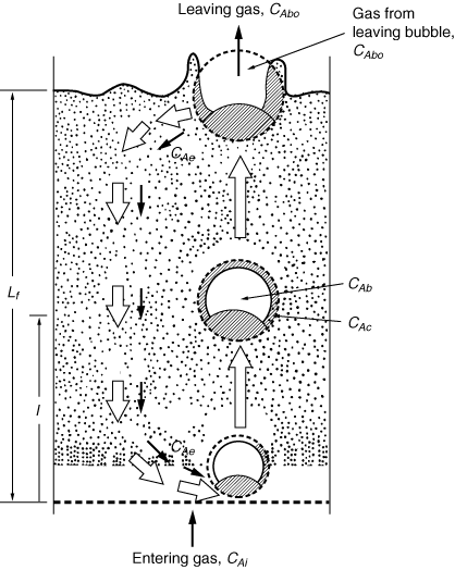 Figure CD12-3.6
Sketch of flow pattern in a fluidized bed for downflow of emulsion gas,
u e /u 0 , <0 or u 0 /u mf > 6 to 11.
Adapted from D. Kunii and O. Levenspiel, Fluidization Engineering
(Melbourne, Fla.: Robert E. Krieger Publishing Co., 1977).
|
|
| |
|
|
|
| |
|
|
|
| |
|
Where C Ab and C Ac are the concentration of A in the bubble and cloud, respectively (mol/dm 3 ), and W Abc represents the number of moles of A transferred from the bubble to the cloud per unit time per unit volume of bubble (mol/ dm 3 s). The concept of basing all mass transfer (and later, all reaction) on the bubble volume proves to simplify the calculations markedly. For the products (e.g., B in A s). The concept of basing all mass transfer (and later, all reaction) on the bubble volume proves to simplify the calculations markedly. For the products (e.g., B in A B) the rate of transfer into the bubble from the cloud is given by a similar equation: B) the rate of transfer into the bubble from the cloud is given by a similar equation: |
|
| |
|
|
|
| |
|
W Bcb =K cb (C Bc -C Bb )
|
(CD12-3.28) |
| |
|
|
|
| |
|
The mass transfer coefficient K bc can also be thought of as an exchange volume q between the bubble and the cloud: |
|
| |
|
|
|
| |
|
W Bcb =q b C Ab -q c C Ac =q 0 (C Ab -C Ac )
|
(CD12-3.29) |
| |
|
|
|
| |
|
where q b is the volume of gas flowing from the bubble to the cloud per unit time per unit volume of bubble, q c the volume of gas flowing from the cloud to the bubble per unit time per unit volume of bubble, and q 0 the exchange volume between the bubble and cloud per unit time per unit volume of bubble (i.e., K bc ; q 0 =q c =q).
Using Davidson's expression for gas transfer between the bubble and the cloud, and then basing it on the volume of the bubble, Kunii and Levenspiel 23 obtained this equation for evaluating K bc |
|
| |
|
|
|
|
Mass transfer between bubble and cloud
|
|
|

|
(CD12-3.30) |
| |
|
where is in cm /s, d b is in cm, D AB is the diffusivity (cm 2 / s), and g is the gravitational constant (980 cm/s 2 ). We note that is in cm /s, d b is in cm, D AB is the diffusivity (cm 2 / s), and g is the gravitational constant (980 cm/s 2 ). We note that |
|
| |
|
|
|
| |
|
Kbc= Kcb
|
|
| |
|
|
|
|
|
and a typical value of K bc is 2 s -1 |
|
| |
|
|
|
| |
|
Similarly, these authors defined a mass transfer coefficient for gas interchange between the cloud and the emulsion: |
|
| |
|
|
|
| |
|

|
(CD12-3.31) |
| |
|
|
|
| |
|
where W Ace is the moles of A transferred from the cloud to the emulsion per unit time per unit volume of bubble. Note that even though this mass transfer does not involve the bubble directly, it is still based on the bubble volume.
Using Higbie's penetration theory and his analogy for mass transfer from a bubble to a liquid, Kunii and Levenspiel 24 developed an equation for evaluating K ce : |
|
| |
|
|
|
|
Mass transfer between cloud and emulsion
|
|
|

|
(CD12-3.32) |
|
|
|
|
|
|
|
where u b is the velocity of the bubble rise in cm /s and the other symbols are as defined below Equation (CD12-3.30). A typical value of K ce is 1 s -1 . K ce can also be thought of as the exchange volume between the cloud and the emulsion.
With knowledge of the mass transfer coefficients, the amount of gas interchange between the phases of a fluidized bed can be calculated and combined to predict the overall mass transfer behavior or reaction behavior of a fluidized-bed process. |
|
|
|
|
| |
|
|
|
|
: |
| |
|
In order to use the Kunii-Levenspiel model to predict reaction rates in a fluidized-bed reactor, the reaction-rate law for the heterogeneous reaction per gram (or other fixed unit) of solid must be known. Then the reaction rate in the bubble phase, the cloud, and the emulsion phase, all per unit of bubble volume, can be calculated. Assuming that these reaction rates are known, the overall reaction rate can be evaluated using the mass transfer relationships presented in the preceding section. All this is accomplished in the following fashion. We consider an nth-order constant-volume catalytic reaction. In the bubble phase |
|
| |
|
|
|
| |
|

|
|
| |
|
|
|
| |
|
in which the reaction rate is defined per unit volume of bubble. In the cloud, |
|
| |
|
|
|
|
|

|
|
| |
|
|
|
| |
|
and similarly in the emulsion, |
|
| |
|
|
|
| |
|

|
|
| |
|
|
|
| |
|
where k e , k c , and k b are the specific reaction rates in the emulsion, cloud, and bubble, respectively. In the latter two equations, the reaction rate is also defined per unit volume of bubble. |
|
| |
|
|
|
| |
|
Mole Balance on the Bubble, Cloud, and Emulsion Phases
Material balances will be written over an incremental height  for substance A in each of the three phases (bubble, cloud, and emulsion) (Figure CD12-3.7). for substance A in each of the three phases (bubble, cloud, and emulsion) (Figure CD12-3.7). |
|
| |
|
|
|
| |
|
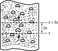 Figure CD12-3.7
Section of a bubbling fluidized bed.
|
|
| |
|
|
|
| |
|
Balance on the Bubble Phase
The amount of A entering at  is the bubble phase by flow, is the bubble phase by flow, |
|
| |
|
|
|
| |
|

|
|
| |
|
|
|
| |
|
A similar expression can be written for the amount of A leaving in the bubble phase in flow at  + +  : : |
|
| |
|
|
|
| |
|

|
|
| |
|
|
|
| |
|
Dividing by  and taking the limit as and taking the limit as  yields yields |
|
| |
|
|
|

|
| |
|
|
|
| |
|
A balance on A in the bubble phase for steady-state operation in section  is is |
|
| |
|
|
|
|
|

|
(CD12-3.33) |
| |
|
|
|
| |
|
|
|
| |
|
Balance on the Cloud Phase
In the material balance on the clouds and wakes in section  , it is easiest to base all terms on the bubble volume. The material balance for the clouds and wakes is , it is easiest to base all terms on the bubble volume. The material balance for the clouds and wakes is |
|
| |
|
|
|
|
|
|
(CD12-3.34) |
| |
|
|
|
| |
|
Balance on the Emulsion Phase
The fraction of the bed in the emulsion phase is 1 -  - -   . The material balance for A in the emulsion results in the following expression for the emulsion-phase material balance on A: . The material balance for A in the emulsion results in the following expression for the emulsion-phase material balance on A: |
|
| |
|
|
|
|
|
|
(CD12-3.35) |
| |
|
|
|
| |
|
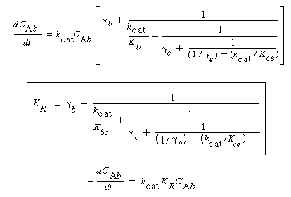
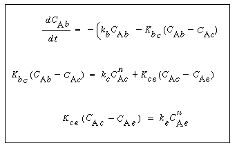
The three material balances thus result in three coupled ordinary differential equations, with one independent variable ( ) and three dependent variables (C Ab , C Ac , C Ae ). These equations can be solved numerically. The Kunii-Levenspiel model simplifies these still further by assuming that the derivative terms on the left-hand side of the material balances on the cloud and emulsion are negligible compared with the terms on the right-hand side. Using this assumption and letting ) and three dependent variables (C Ab , C Ac , C Ae ). These equations can be solved numerically. The Kunii-Levenspiel model simplifies these still further by assuming that the derivative terms on the left-hand side of the material balances on the cloud and emulsion are negligible compared with the terms on the right-hand side. Using this assumption and letting
t = /u b (i.e., the time the bubble has spent in the bed), the three equations take the form /u b (i.e., the time the bubble has spent in the bed), the three equations take the form |
|
| |
|
|
|
|
|
|
(CD12-3.36)
(CD12-3.37)
(CD12-3.38) |
|
|
one differential equation and two algebraic equations. In all equations,  represents the gram-moles per second reacted in the particular phase per volume of bubbles. represents the gram-moles per second reacted in the particular phase per volume of bubbles. |
|
| |
|
|
|
| |
|
Partitioning of the Catalyst
|
|
| |
|
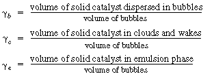
To solve these equations, it is necessary to have values of k b , k c , and k e . Three new parameters are defined: |
|
| |
|
|
|
| |
|
|
|
| |
|
|
|
| |
|
|
|
| |
|
First, the specific reaction rate of solid catalyst, k cat must be known. It is normally determined from laboratory experiments. The term k cat  represents the gram-moles reacted per volume of solid catalyst. Then represents the gram-moles reacted per volume of solid catalyst. Then |
|
| |
|
|
|
Relating the
specific reaction
rates
|
|
|
|
(CD12-3.39) |
| |
|
|
|
| |
|
The term k' is the specific reaction rate per weight of catalyst. |
|
| |
|
|
|
|
The value of  b ranges between 0.001 and 0.01, with 0.005 being the more typical number. The volume fraction of catalyst in the clouds and wakes is 1 - b ranges between 0.001 and 0.01, with 0.005 being the more typical number. The volume fraction of catalyst in the clouds and wakes is 1 -  . The volume of cloud and wakes per volume of bubble is . The volume of cloud and wakes per volume of bubble is |
|
| |
|
|
|
| |
|

|
|
| |
|
|
|
| |
|
so the expression for  c is c is |
|
| |
|
|
|
The volume of
catalysts in the clouds
is  c c
|
|
|

|
(CD12-3.40) |
| |
|
|
|
| |
|
It turns out that the value of  is normally far from insignificant in this expression for is normally far from insignificant in this expression for  c and represents a weakness in the model because there does not yet exist a reliable method for determining c and represents a weakness in the model because there does not yet exist a reliable method for determining  . The typical values of . The typical values of  c range from 0.3 to 0.4. The value of c range from 0.3 to 0.4. The value of  c can be quite incorrect on occasion, in particular, a value of c can be quite incorrect on occasion, in particular, a value of  = 1. = 1.
The volume fraction of the solids in the emulsion phase is again 1 -  . The volume of emulsion per volume of bubble is . The volume of emulsion per volume of bubble is |
|
| |
|
|
|
| |
|

|
|
| |
|
|
|
| |
|
so the expression for  e is e is |
|
| |
|
|
|
The volume of
catalysts in the clouds is  e e
|
|
|

|
(CD12-3.41) |
| |
|
|
|
| |
|
Typical values of  b , b ,  c , and c , and  e are 0.005, 0.2, and 1.5, respectively. Using the expressions given above, the three balance equations become e are 0.005, 0.2, and 1.5, respectively. Using the expressions given above, the three balance equations become |
|
| |
|
|
|
|
For reactors other than first or zero order these equations must be solved numerically.
|
|
|
 |
(CD12-3.42)
(CD12-3.43)
(CD12-3.44) |

 . The equation recommended by Kunii and Levenspiel 21 is


 s). The concept of basing all mass transfer (and later, all reaction) on the bubble volume proves to simplify the calculations markedly. For the products (e.g., B in A
 B) the rate of transfer into the bubble from the cloud is given by a similar equation:
 is in cm /s, d b is in cm, D AB is the diffusivity (cm 2 / s), and g is the gravitational constant (980 cm/s 2 ). We note that


 for substance A in each of the three phases (bubble, cloud, and emulsion) (Figure CD12-3.7).
 is the bubble phase by flow,

 and taking the limit as
  yields


 -
- 

 represents the gram-moles per second reacted in the particular phase per volume of bubbles.
 represents the gram-moles reacted per volume of solid catalyst. Then

 b ranges between 0.001 and 0.01, with 0.005 being the more typical number. The volume fraction of catalyst in the clouds and wakes is 1 -


