Chapter 15: Diffusion and Reaction in Porous Catalysts
Professional Reference Shelf
R12.2 Trickle Bed Reactors
|
|
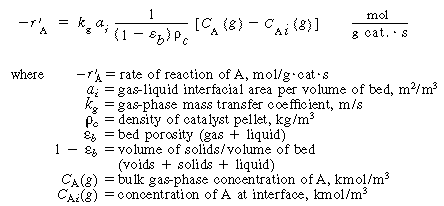
Transport from bulk |
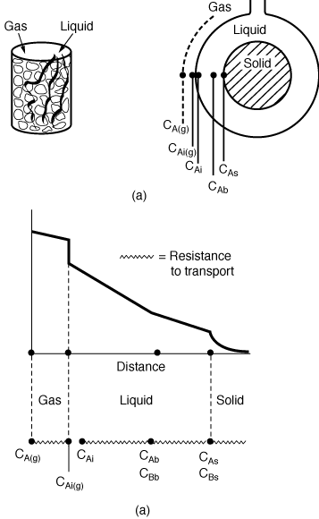
Figure R12.2-1 |
||
| 2. Equilibrium at gas-liquid interface: | |||
|
|
(R12.2-3) | ||
| C Ai = concentration of
A in liquid at the interface H = Henry's constant |
|||
| 3. Transport from interface to bulk liquid:
|
|||

|
(R12.2-4) | ||
| where | |||
| k 1
= liquid-phase mass transfer coefficient, m/s C Ai = concentration of A in liquid at the interface, kmol/m 3 C Ab = bulk liquid concentration of A, kmol/m 3 |
|||
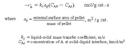
| 4. Transport from bulk liquid to external catalyst surface: | |||
|
(R12.2-5) | ||
| 5. Diffusion and reaction in the pellet. If we assume a first-order reaction in dissolved gas A and in liquid B, we have | |||
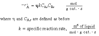
|
(R12.2-6) | ||
| Combining Equations (R12.2-2) through (R12.2-6) and rearranging in a manner identical to that leading to the development of Equation (12-89) for slurry reactors, we have | |||
|
The overall rate equation for A |

|
(R12.2-7) | |
| that is, | |||
|
|
(R12.2-8) | ||
where is the overall transfer coefficient for the gas into
the pellet (m 3 of gas/g cat. is the overall transfer coefficient for the gas into
the pellet (m 3 of gas/g cat. s). A mole balance on species A gives s). A mole balance on species A gives
|
|||
|
|
(R12.2-9) | ||
| We next consider the transport and reaction of species B, which does not leave the liquid phase. | |||
| 6. Transport of B from bulk liquid to solid catalyst interface: | |||
|
|
(R12.2-10) | ||
| where C B and C Bs are the concentrations of B in the bulk fluid and at the solid interface, respectively. | |||
| 7. Diffusion and reaction of B inside the catalyst pellet: | |||
|
|
(R12.2-11) | ||
| Combining Equations (12-33) and (12-34) and rearranging, we have | |||
|
The overall rate |
|
(R12.2-12) | |
| A mole balance on species B gives | |||
|
Mole balance on B |
|
(R12.2-13) | |
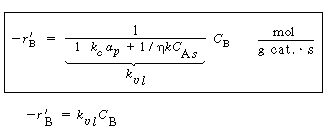
One notes that the surface concentrations of A and B, CAs and C B
s , appear in the denominator of the overall transport
coefficients and and . .
|
|||
| Consequently, Equations (R12.2-7), (R12.2-9), (R12.2-12), and (R12.2-13) must be solved simultaneously. In some cases analytical solutions are available, but for complex rate laws, one resorts to numerical solutions. 1 However, we shall consider some limiting situations. | |||
R12.2-B Limiting Situations |
|||
Mass Transfer of the Gaseous Reactant Limiting. For this situation
we assume that either the first three terms in the denominator of Equation (R12.2-7)
are dominant or that the liquid-phase concentration of species B does not vary significantly
through the trickle bed. For these conditions
|
|||
is constant and we can integrate the mole balance. For negligible
volume change = 0, then = 0, then
|
|||
|
Catalyst weight |
|
(R12.2-14) | |
Mass Transfer and Reaction of Liquid Species Limiting. Here
we assume that the liquid phase is entirely saturated with gas throughout the column.
As a result, C As is a constant.
Consequently, we can integrate the combined mole balance and rate law to give  . .
|
|||
|
Catalyst weight |
|
(R12.2-15) | |
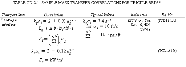
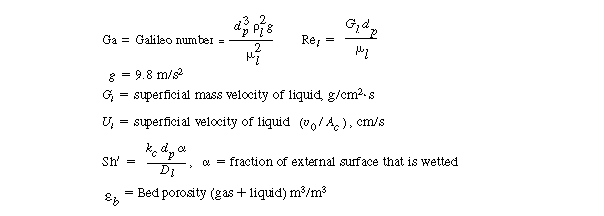
R12.2-C Evaluating the Transport CoefficientsThe mass transfer coefficients, k g , k l , and k c depend on a number of variables, such as type of packing, flow rates, wetting of particle, and geometry of the column, and as a result the correlations vary significantly from system to system. Consequently, we will not give all the correlations here but instead will give correlations for particular systems and refer the reader to four specific references where other correlations for trickle bed reactors may be found. 2 Typical correlations are given in Table R12.2-1. Note that the correlation for organic particles tends to under predict the transport coefficient. |
|||
|
Criterion for assuming |
The representative correlations given in Table R12.2-1 assume complete
wetting of the catalyst particles. Corrections for incomplete wetting as flow regimes,
pressure-drop equations, and other mass transfer correlations can be found in the
reviews by Shah, Smith, and Satterfield.
3 The plug-flow design equation may be applied successfully provided that the ratio of reactor length L to particle diameter d p satisfies the criterion (Satterfield, 1975) |
||
|
|
(R12.2-16) | ||
| where
Pe = Péclet number = d p U
l /D AX D AX = axial dispersion coefficient n = reaction order |
|||
|

|

|
|

|
|
aAlso see N. Midoux, B. I. Morsi, M. Purwasasmita, A. Laurent, and J. C. Charpentier, Chem. Eng. Sci., 39, 781 (1984), for a comprehensive list of correlations. b In some cases this gives a low estimate of k l a i ; see M. Herskowitz and J. M. Smith, AIChE J., 29, 1983); F. Turek and R. Lange, Chem. Eng. Sci., 36 569 (1981) |
| The CSTR design equations apply to the trickle bed when 4 | |||
|
|
(R12.2-17) | ||
| Techniques for determining the single-phase axial dispersion coefficient are given in Chapter 14. | |||
| Example R12.2-1 Trickle Bed Reactor |
|||
| The material presented in this example is meant to serve as an introduction to trickle bed reactors. Other worked-out trickle bed example problems can be found in an article by Ramachandran and Chaudhari 6. In addition, the hyrodesulfurication of a hydrocarbon in a trickle bed reactor is given in detail by Tarhan7. |
 to
to in. in diameter. The
pores of the catalyst are filled with liquid. In petroleum refining, pressures of
34 to 100 atm and temperatures of 350° to 425°C are not uncommon. A pilot-plant
trickle bed reactor might be about 1 m deep and 4 cm in diameter. Trickle beds are
used in such processes as the hydrodesulfurization of heavy oil stocks, the hydrotreating
of lubricating oils, and reactions such as the production of butynediol from acetylene
and aqueous formaldehyde over a copper acetylide catalyst. It is on this latter type
of reaction,


