Chapter 16: Distributions of Residence Times for Chemical Reactors
Topics
| Residence Time Distribution | top |
We shall use the RTD to characterize existing (i.e. real) reactors and then use it to predict exit conversions and concentrations when reactions occur in these reactors.
Inject a tracer and measure exit concentration, CT(t).
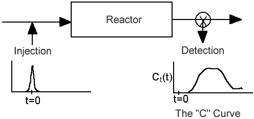
From the exit tracer concentration we can determine the following information:
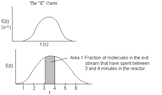
A. RTD (Residence Time Distribution) Function (E(t))

 = Fraction of molecules exiting the reactor that have spent a time between (t) and
(t + dt) in the reactor.
B. The Cumulative Distribution Function F(t)
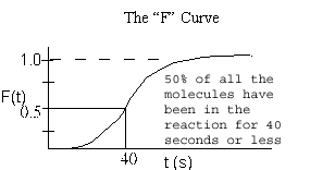
 = Fraction of molecules exiting the reactor that have spent a time t or less in the reactor.
 = Fraction of molecules that have spent a time t or greater in the reactor.
C. Definitions
1. Mean Residence Time
2. Variance

3. Space Time - For no dispersion/diffusion and v = v0, the space time equals the mean residence time.

4. Internal Age Distribution,
 = Fraction of molecules inside the reactor that have been inside the reactor between a time
 and
and .
.

5. Life Expectancy
 = Fraction of molecules inside the reactor with age
 that are expected to leave the reactor in a time
 to
to .
.
From our experimental data of the exit tracer concentration from pulse trace test
|
t(min) |
: |
0 |
1 |
2 |
3 |
4 |
5 |
6 |
|
C(mg/m3) |
: |
0 |
0 |
0.1 |
0.2 |
0.3 |
0.1 |
0 |
We can obtain

 ->
-> ->
->  ->
->  ->
->
| RTD for Ideal Reactors | top |
 for Ideal Reactors for Ideal Reactors
|
||
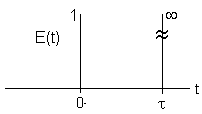
| PFR- Inject a pulse at t=0 | 
|
|
Dirac Delta Function
|
||
| CSTR | 
|

|
|
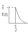
| Laminar (LFR) | 
|
|

|
| RTD to Diagnose Faulty Operation | top |
Experimentally injecting and measureing the tracer in a laminar flow reactor can be a difficult task, if not a nightmare. For example, if one uses tracer chemicals that are photo-activated as they enter the reactor, the analysis and interpretation of E(t) from the data becomes much more involved.
Diagnostics and Troubleshooting
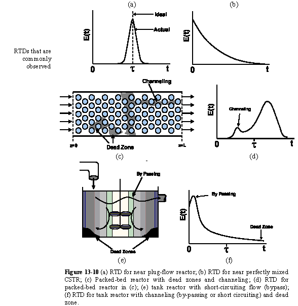
The CSTR
| Concentration |  |
||
| RTD Function |  |
||
| Cumulative Function |  |
||
| Space Time |  |
a. Perfect Operation

b. Passing (BP)

c. Dead Volume
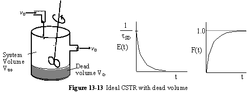
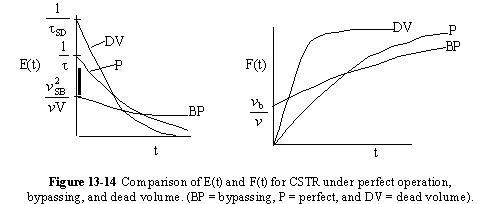
A summary for ideal CSTR mixing volume is shown in Figure 13-14
Tubular Reactor
A similar analysis to that for a CSTR can be carried out on a tubular reactor.
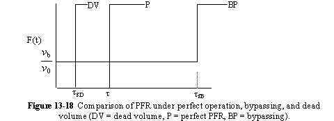
a. Perfect Operation of PFR (P)

b. PFR with Channeling (Bypassing, BP)

c. PFR with Dead Volume (DV)
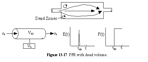
A summary for PRF is shown in Figure 13-18
In addition to its use in diagnosis, the RTD can be used to predict conversion in existing reactors when a new reaction is tried in an old reactor. However, the RTD is not unique for a given system, and we need to develop models for the RTD to predict conversion.
* All chapter references are for the 4th Edition of the text Elements of Chemical Reaction Engineering .


