Kinect Car
University of Michigan
EECS 373 Winter 2011
Hardware Design
Click here for detailed diagram
- We used two Smartfusion boards in our project, one on the car and the other connected to the Linux box. The board on the car used hardware to perform various car controls such as wheel motors and camera servos. The other board was slightly less complex, implementing hardware for serial communication with the Linux box as well as the LCD display. Both boards have a SPI module in the hardware used for the radio communication.
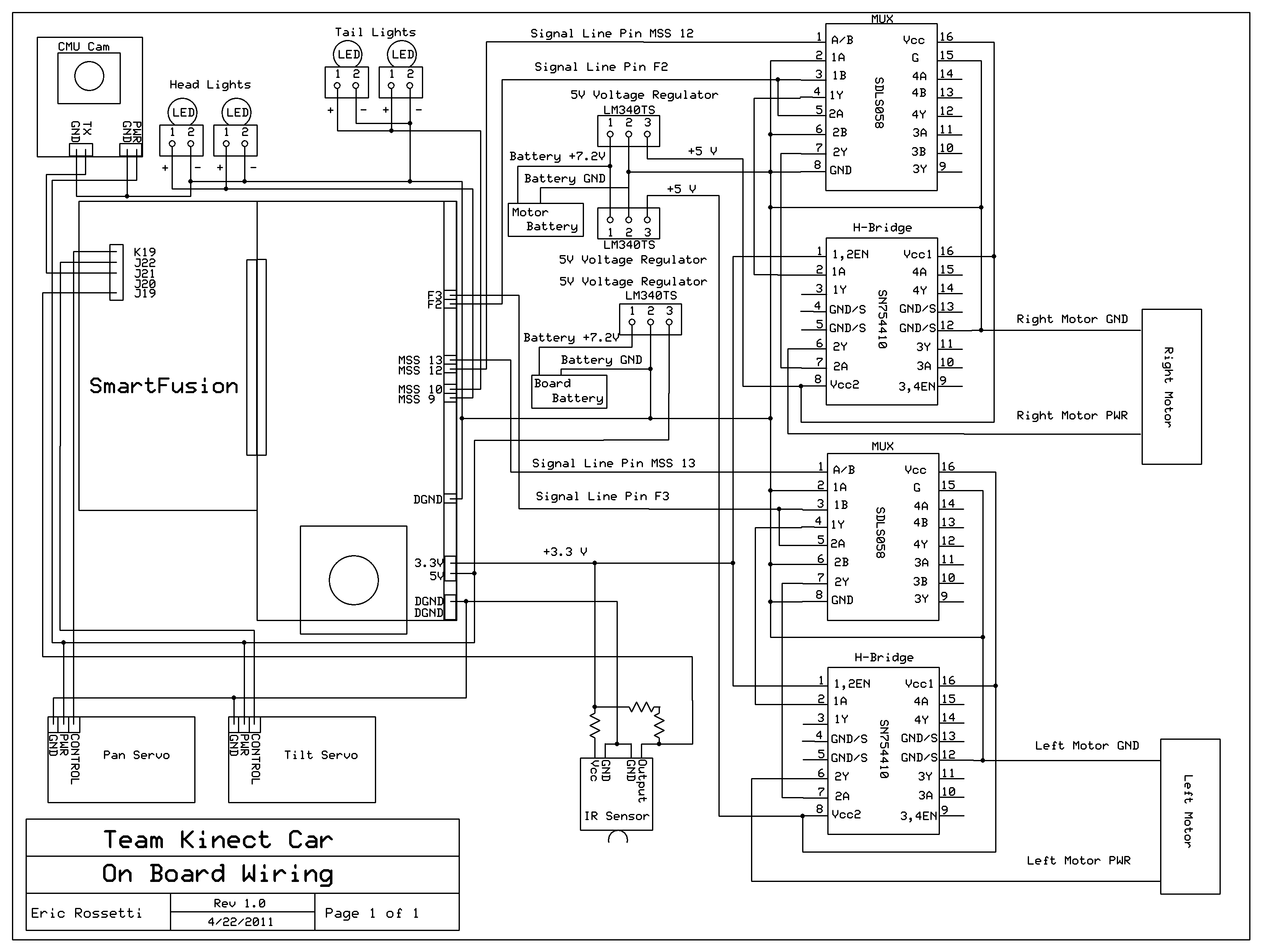
KC's on-car SmartFusion Board
We used the built in MSS timer to implement a few timed operations. The first timed operation was a blinking tail light when the car was in reverse. The second was to recover by driving away from a hazard for a certain amount of time. The final timer operation was to act as a watchdog in case our two-way radio communication stalled. All of these timer implementations were comparisons. Wheel motors, servo controls, LEDs, and the rear sensor were all allocated to GPIO pins on the break out board. The CMU camera located on the car did it's own image processing then communicated with the on-car board via serial data transfer using a core UART module in the hardware. As mentioned, we built an infrared sensor to detect and avoid edges. This sensor sends a high signal when it is not picking up an infrared reflection from the surface it is pointed down at. We are implementing PWM (pulse-width modulated) signals for variable wheel speed as well as camera servo control. The two wheels on the car are both bi-directional, which is produced using a digital mux feeding an H-bridge for each wheel in the drive control circuitry.
Kinect Side SmartFusion Board
We also used the MSS timer as a watchdog for our two-way radio communication on this board. We used an LCD screen to display the CMU camera data we were receiving from the car. The LCD communicated with our board via serial data transfer. The Kinect itself is merely a series of high quality cameras, two infrared depth cameras and one visual spectrum camera, which is sent to the Linux computer via USB and interpreted by NITE and openNI software. The drive control data is sent to the SmartFusion via the MAX232 voltage conversion circuit. This circuit regulates the standard serial voltages from the computer down to the 0-5V range that the SmartFusion pins can handle. The control information from the Linux box as well as the LCD display data both used a UART module in the hardware on the board for serial transfer.