Figures
This page contains figure files for figures from the book The Science of Music by Mark Newman. You can also download all figures in a single ZIP file here. A few figures are not included because of licensing limitations.
Chapter 1: Sound
| Format | Figure | Description |
|---|
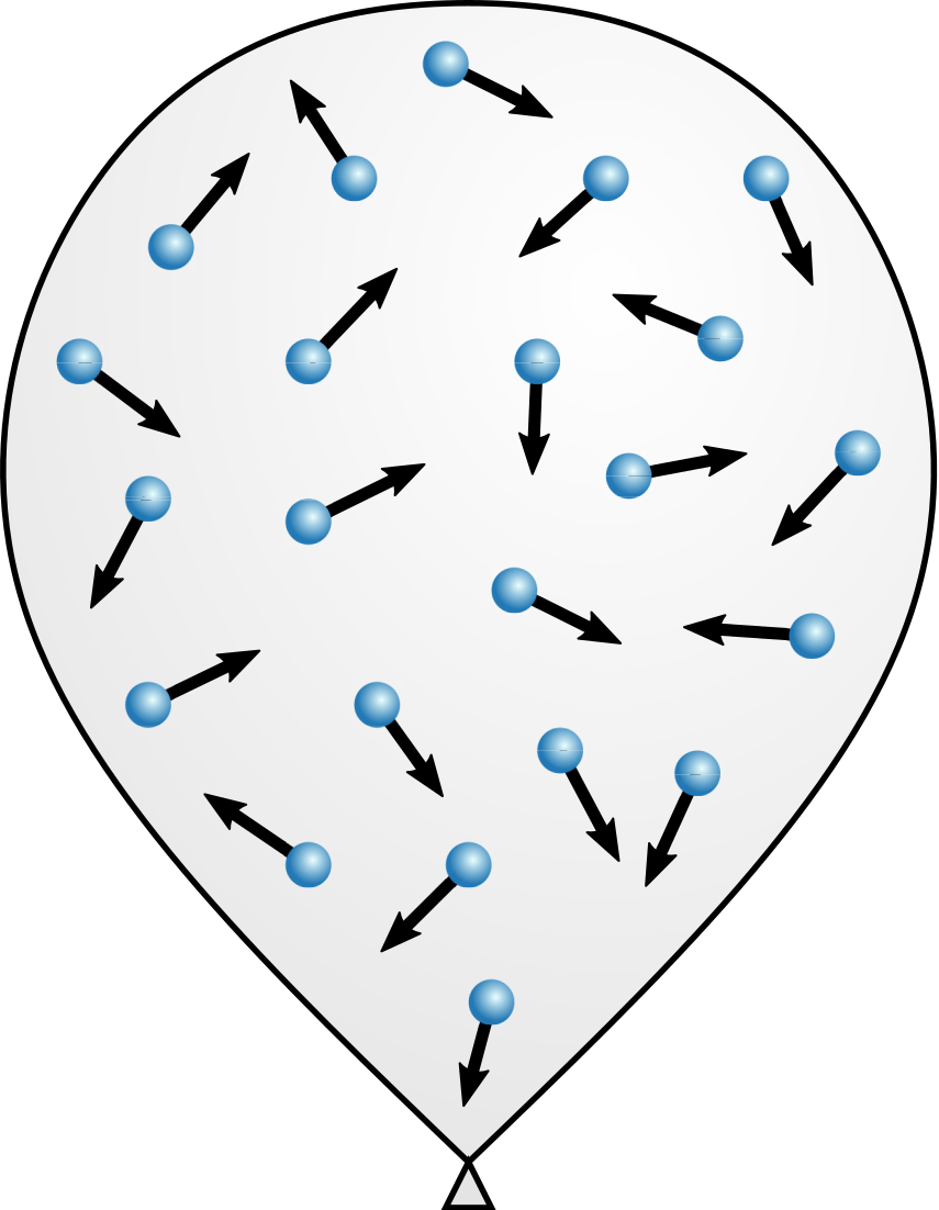
| PDF | PNG | – | Air inside a balloon
|
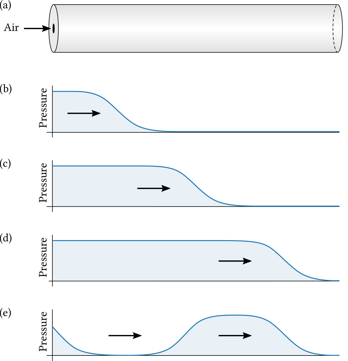
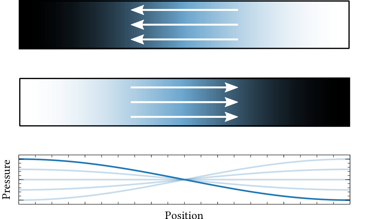
| PDF | PNG | 1.1 | Motion of a pressure wave in a tube
|
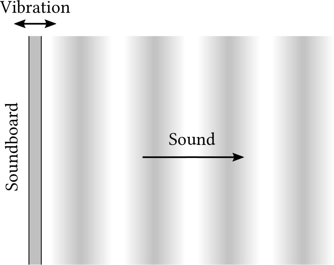
| PDF | PNG | 1.2 | Sound production by a vibrating surface
|
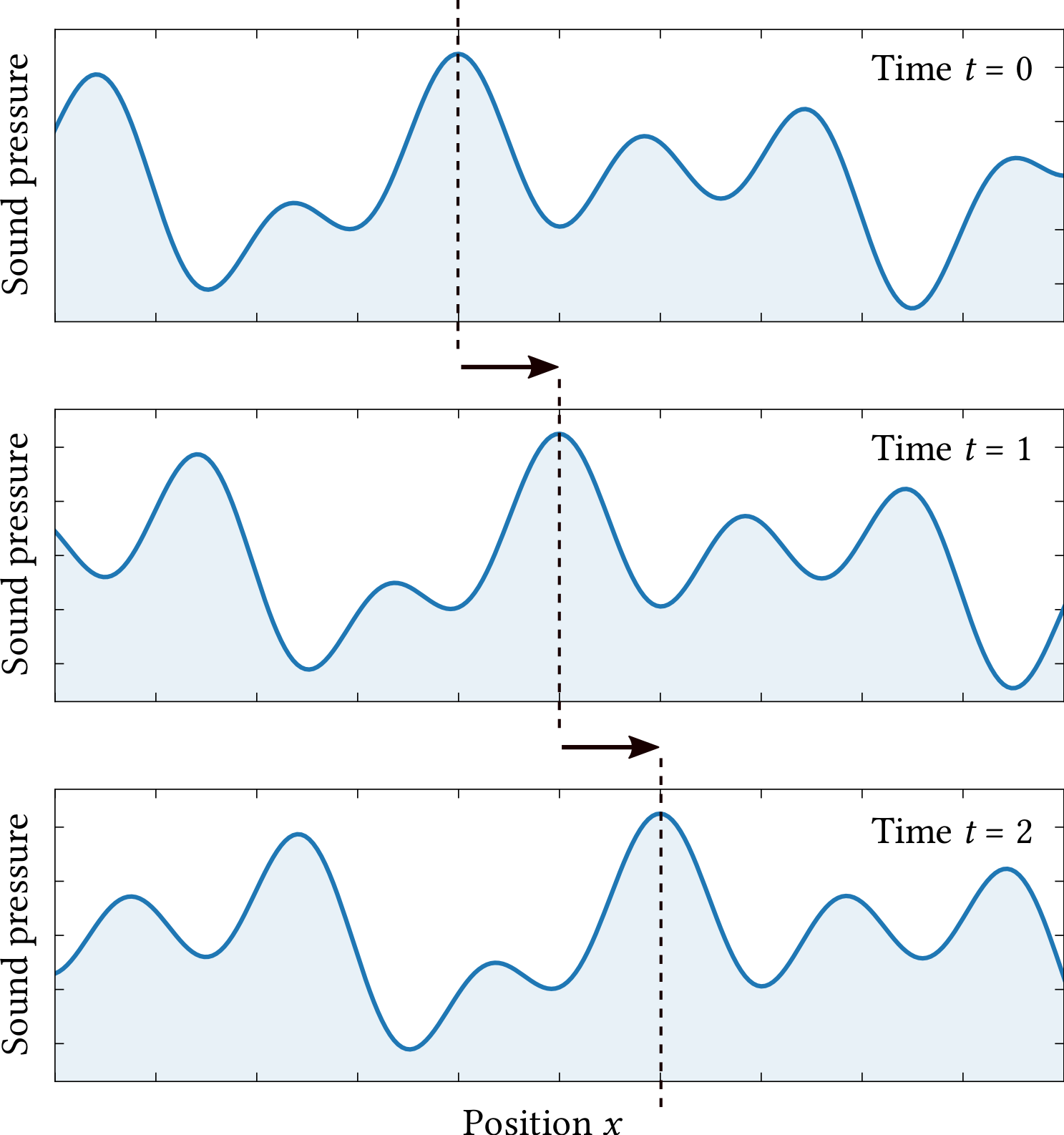
| PDF | PNG | 1.3 | Motion of a sound wave over time
|
| PDF | PNG | 1.4 | A sound waveform
|
| PDF | PNG | 1.5 | A sound wave traveling in a tube
|
Chapter 2: Frequency and pitch
| Format | Figure | Description |
|---|
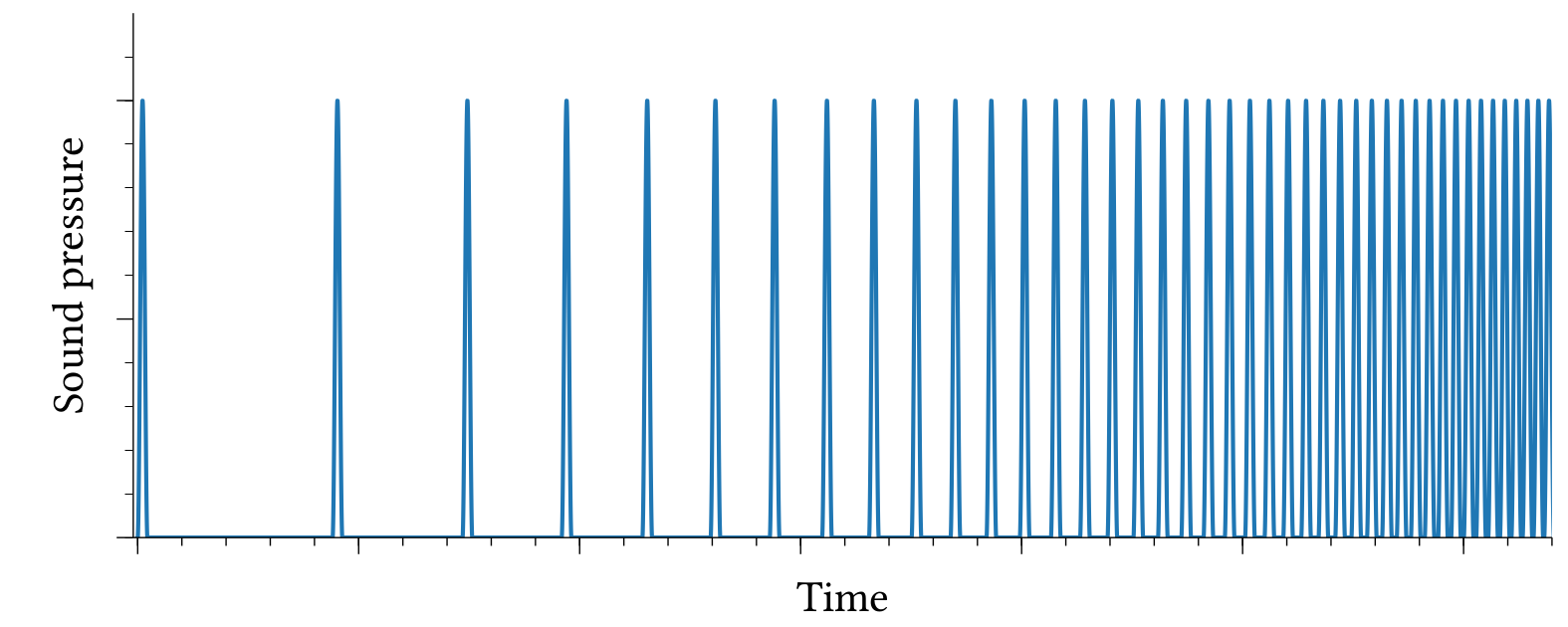
| PDF | PNG | 2.1 | Accelerating series of clicks
|
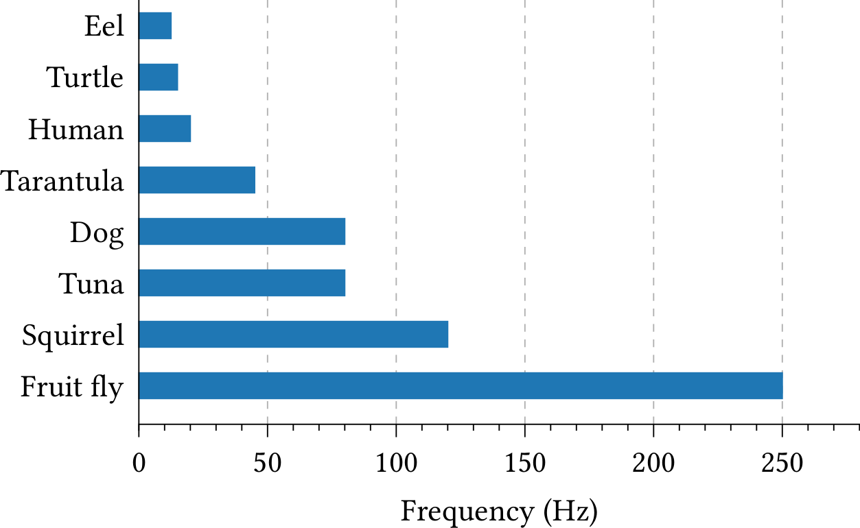
| PDF | PNG | 2.2 | Flicker fusion rate
|
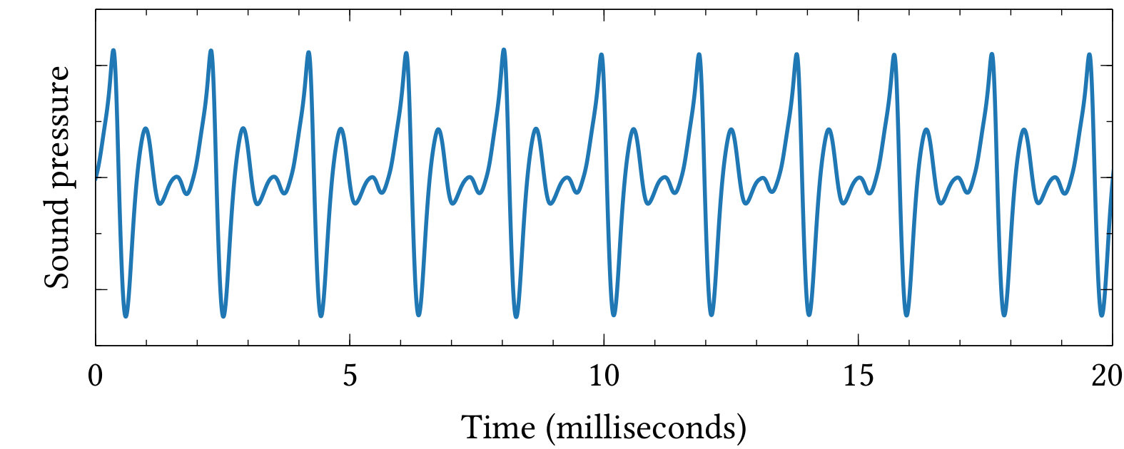
| PDF | PNG | 2.3 | Trumpet waveform
|
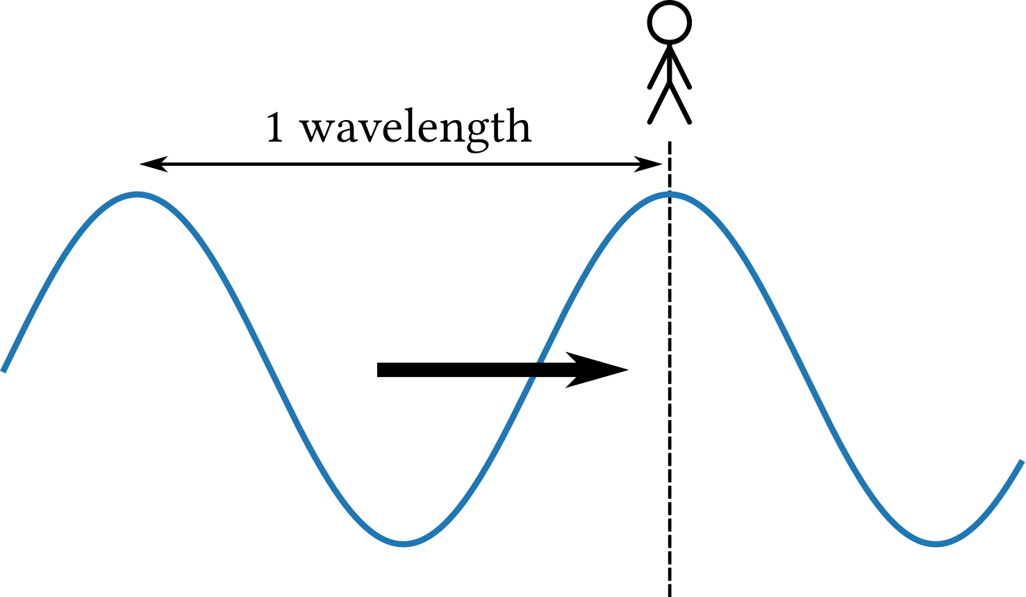
| PDF | PNG | 2.4 | Wavelength of a sound wave
|
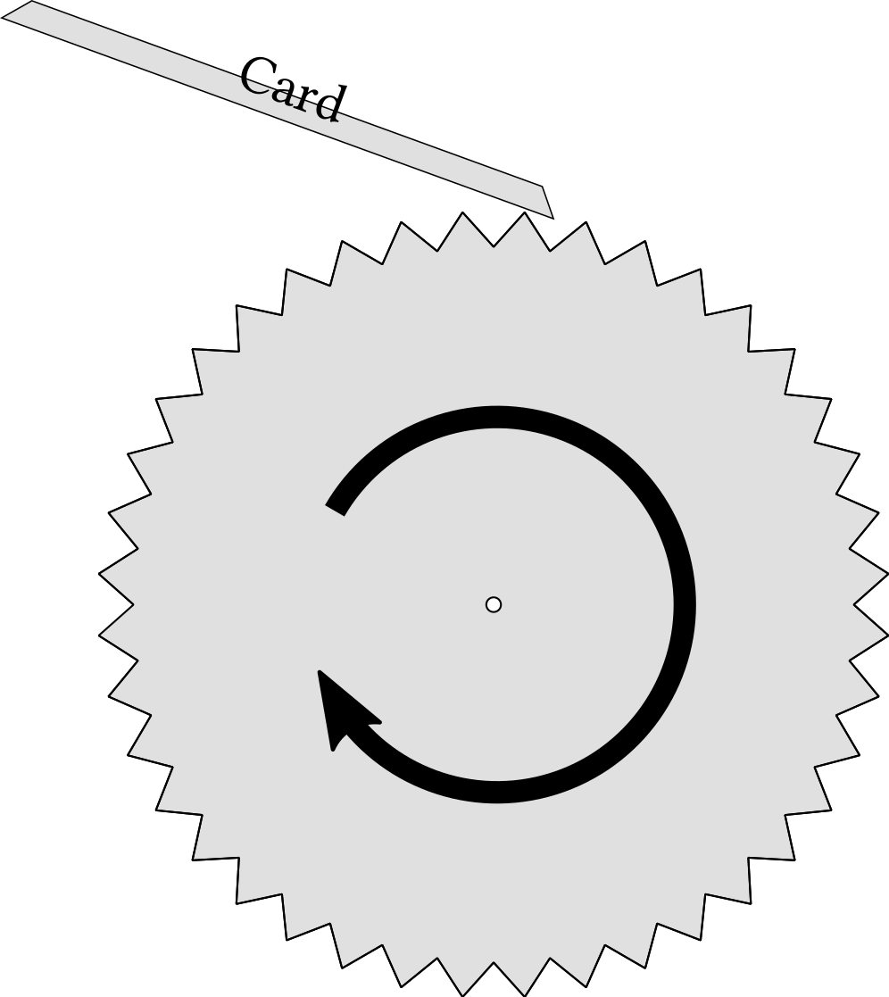
| PDF | PNG | 2.5 | Experiment to measure frequency
|
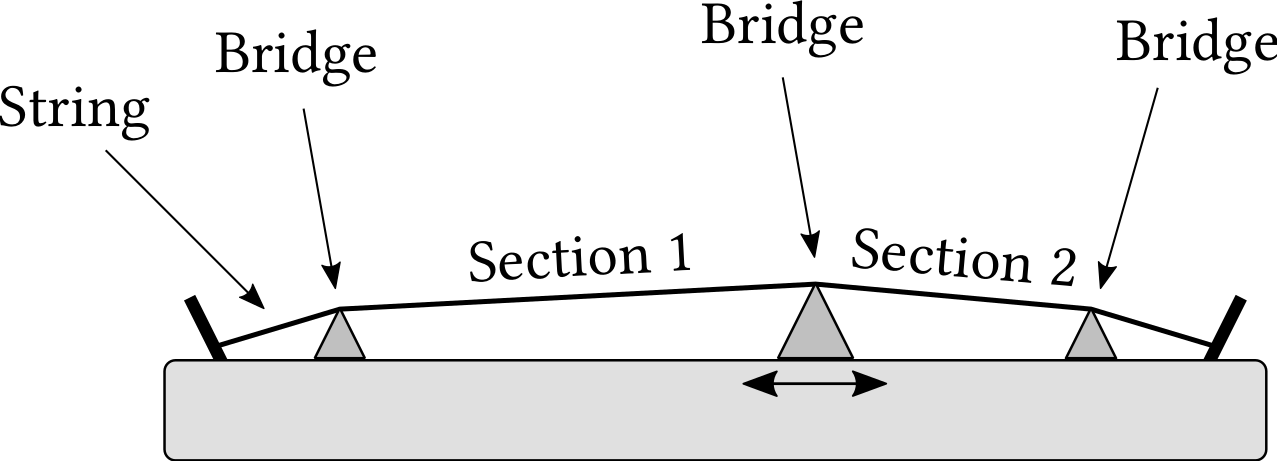
| PDF | PNG | 2.6 | A simple one-stringed musical instrument
|
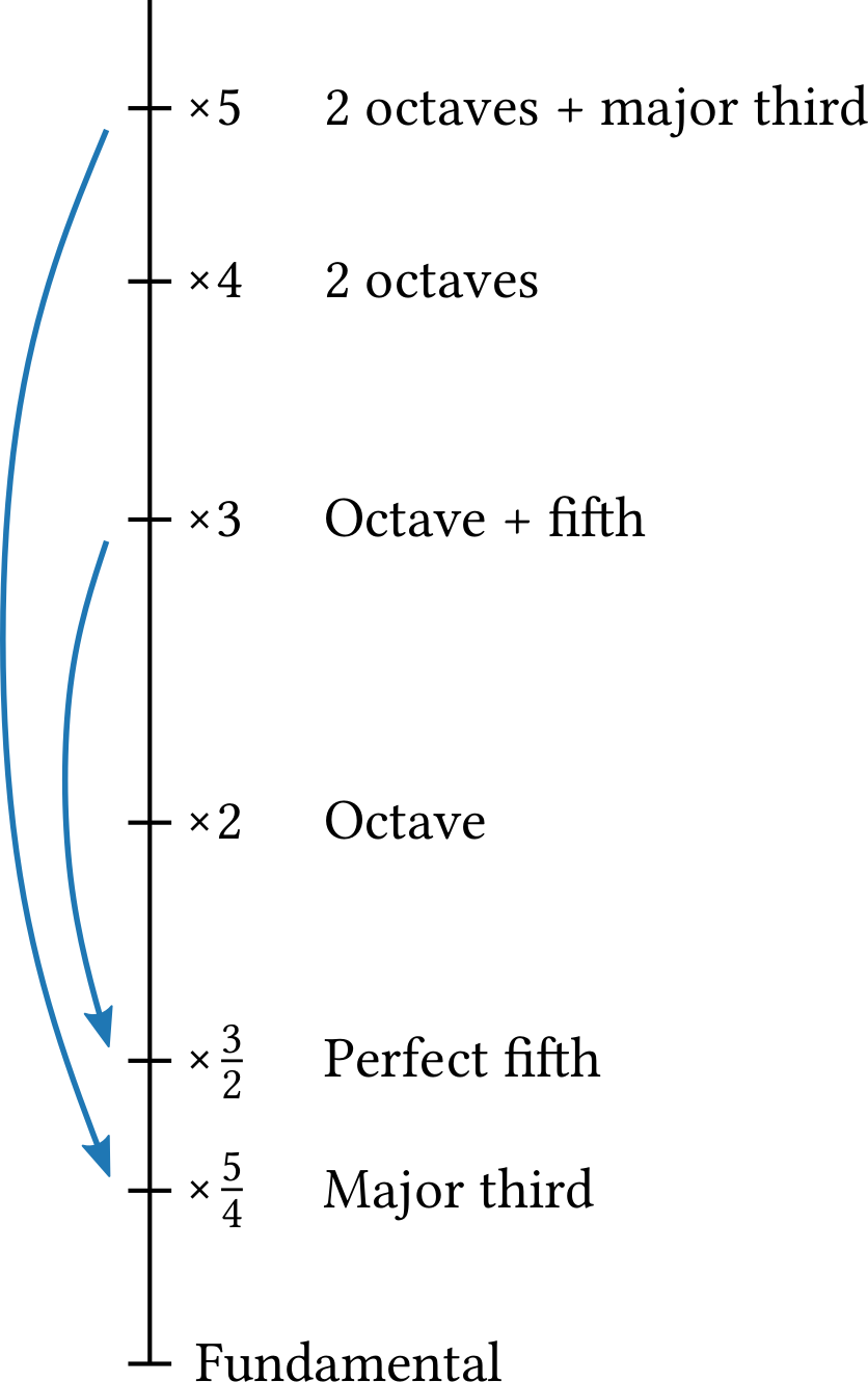
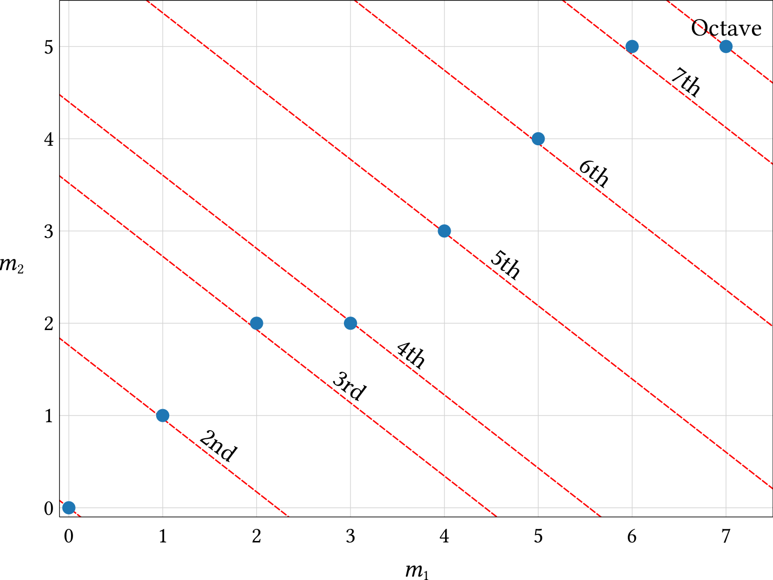
| PDF | PNG | 2.7 | Frequencies of notes in a major chord
|
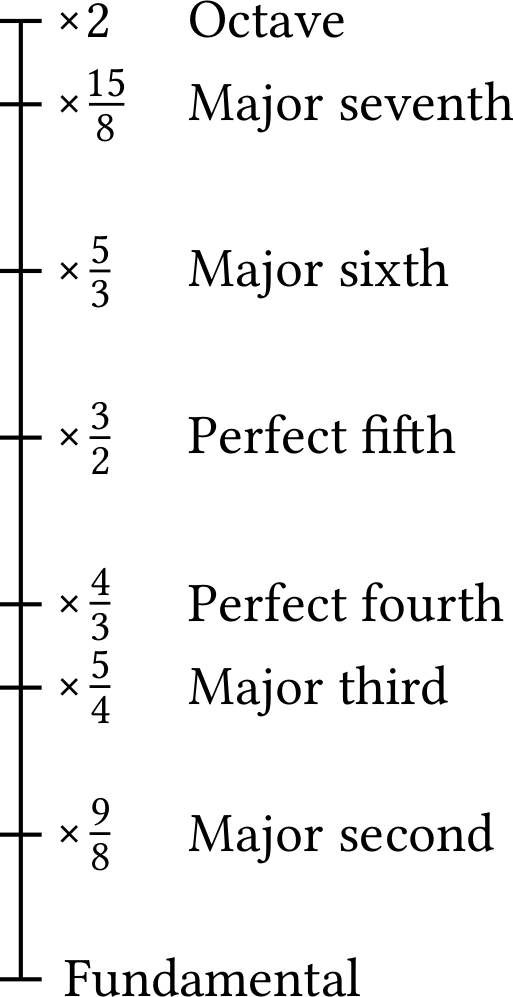
| PDF | PNG | 2.8 | Frequencies of notes in a major scale
|
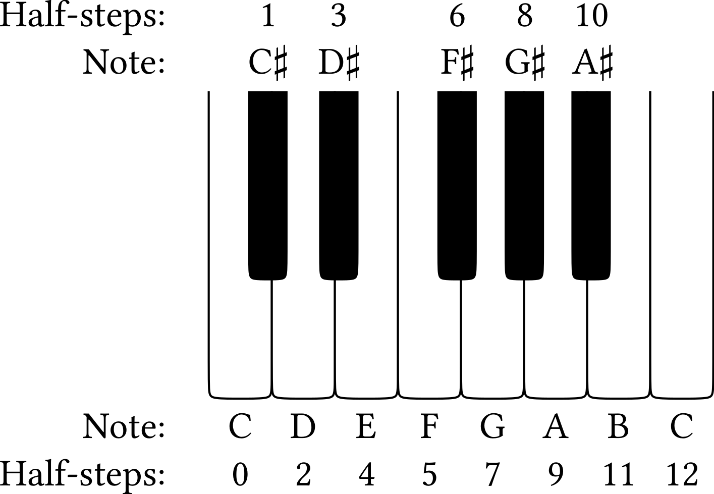
| PDF | PNG | 2.9 | One octave of piano keys
|
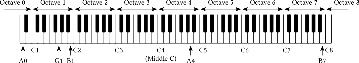
| PDF | PNG | 2.10 | The piano keyboard
|
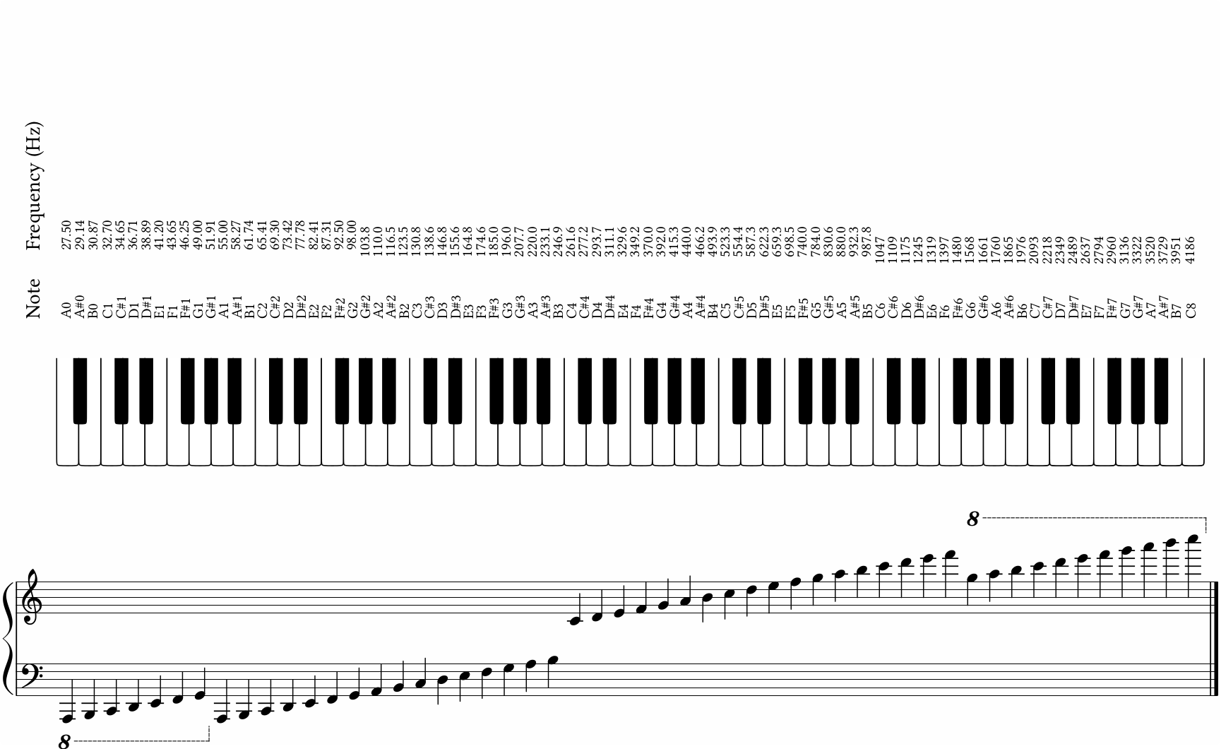
| PDF | PNG | 2.11 | Names and frequencies of notes on the piano keyboard
|
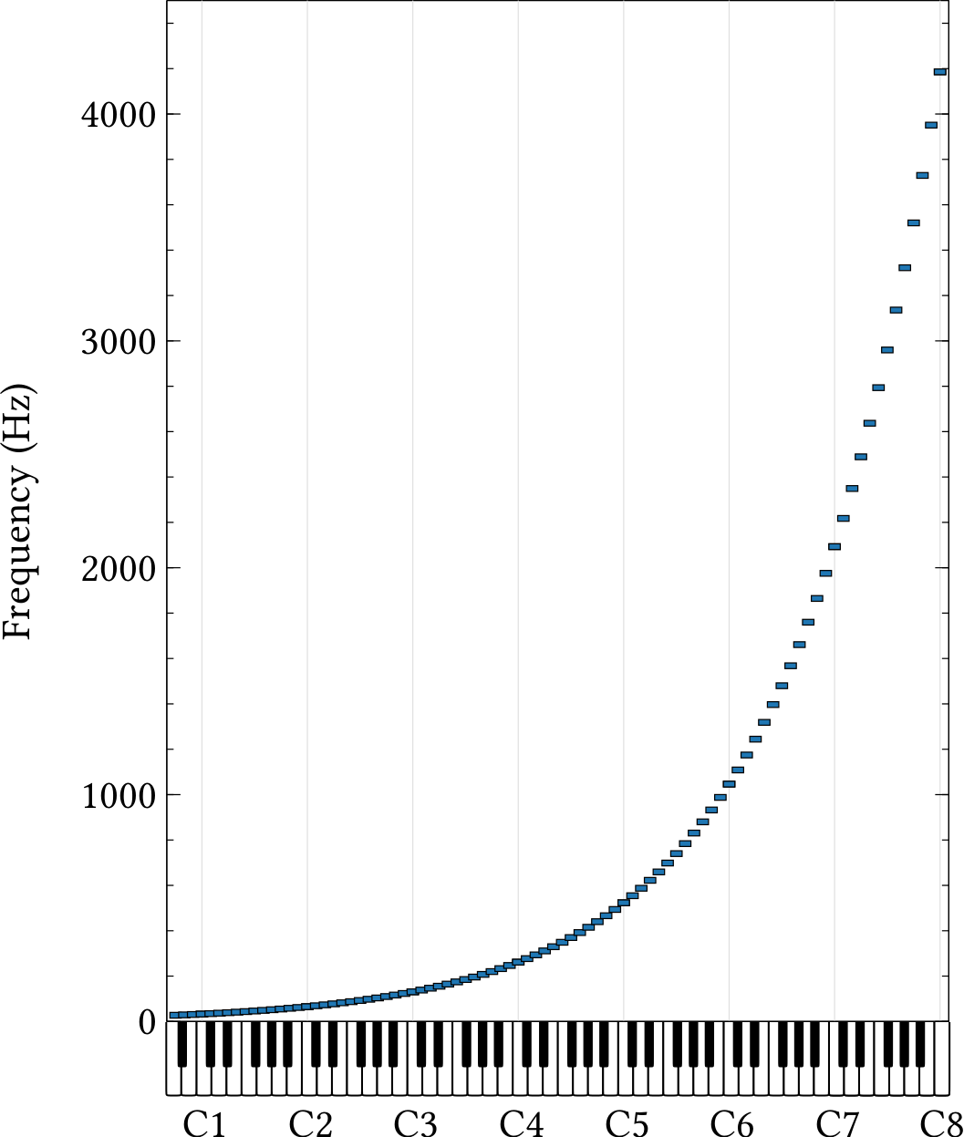
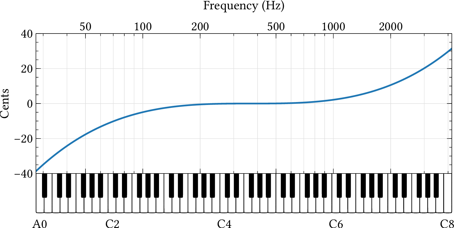
| PDF | PNG | 2.12 | Frequencies of all notes on the piano
|
| PDF | PNG | 2.13 | Pythagorean and equal temperament major scales
|
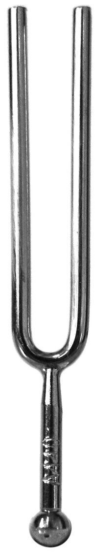
| JPEG | | 2.14 | Tuning fork
|
Chapter 3: Amplitude and loudness
| Format | Figure | Description
|
|---|
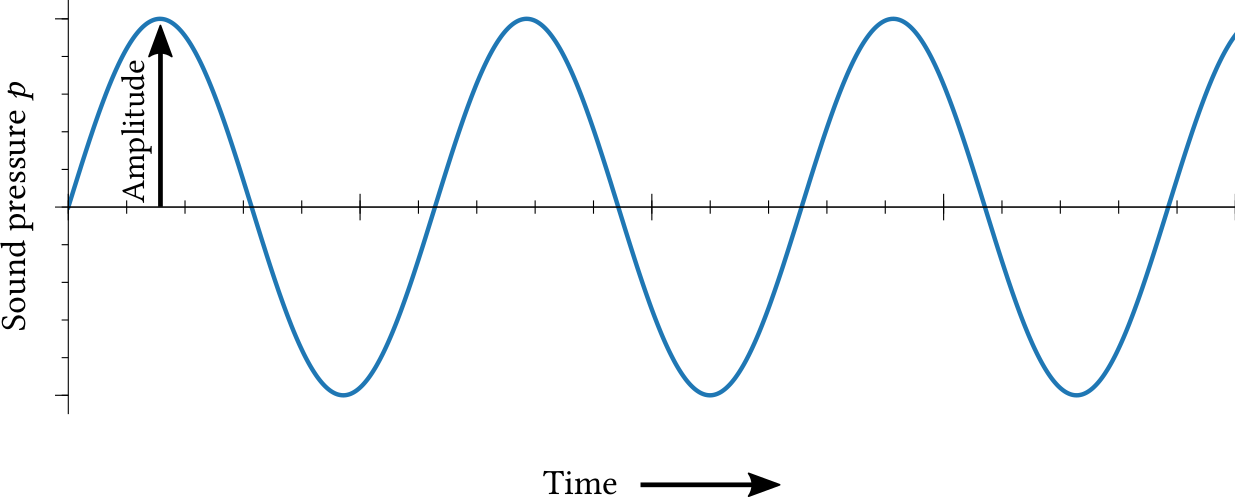
| PDF | PNG | 3.1 | Amplitude
|
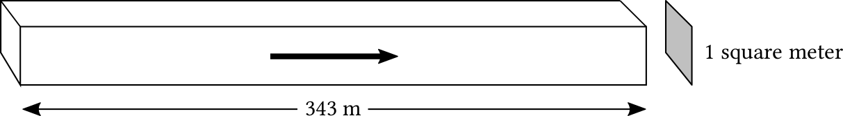
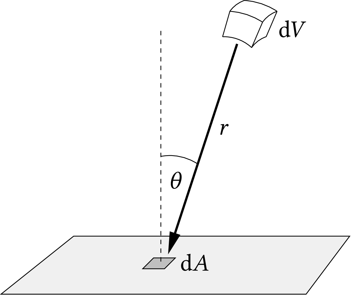
| PDF | PNG | 3.2 | Energy density in a sound wave
|
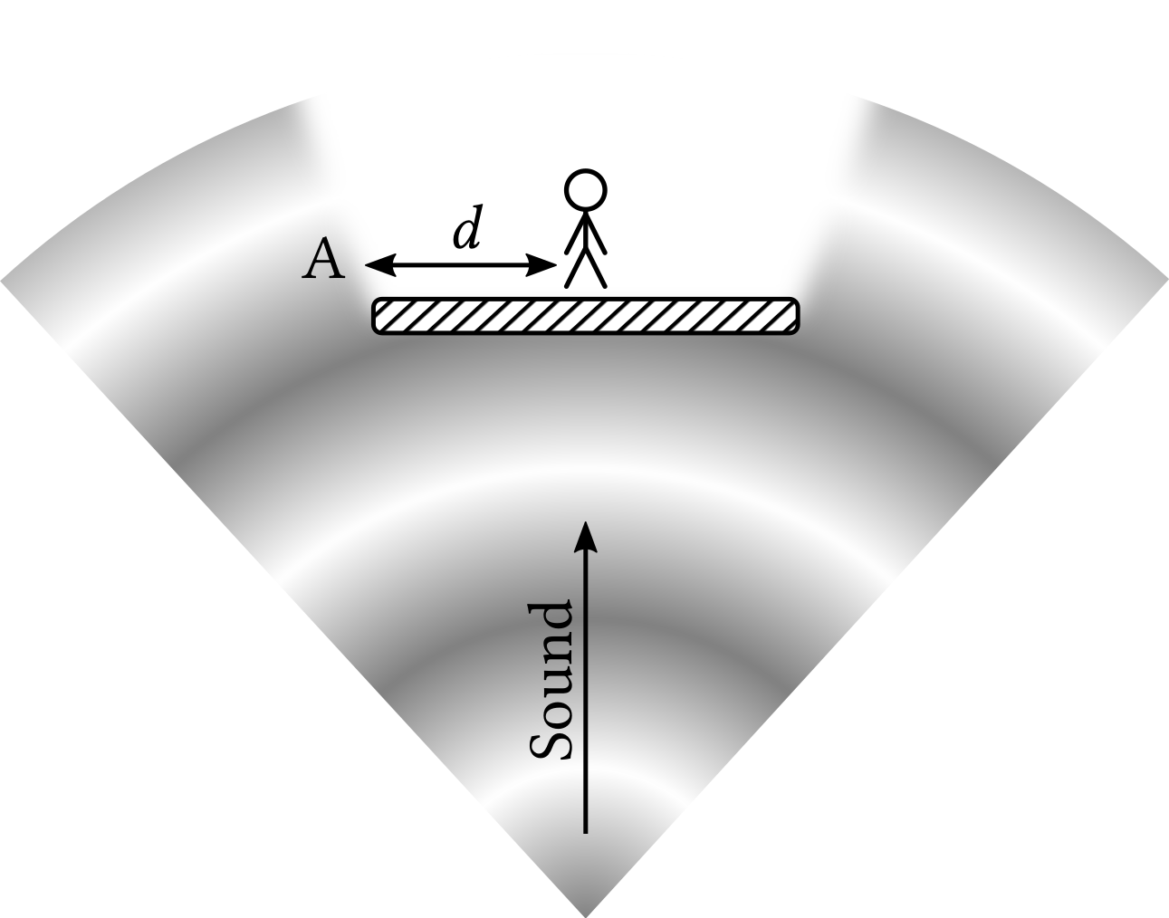
| PDF | PNG | 3.3 | Sound wave blocked by a wall
|
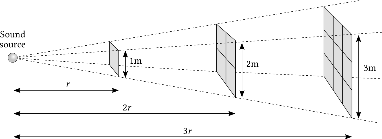
| PDF | PNG | 3.4 | Variation of sound intensity with distance
|
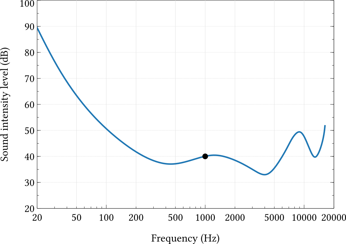
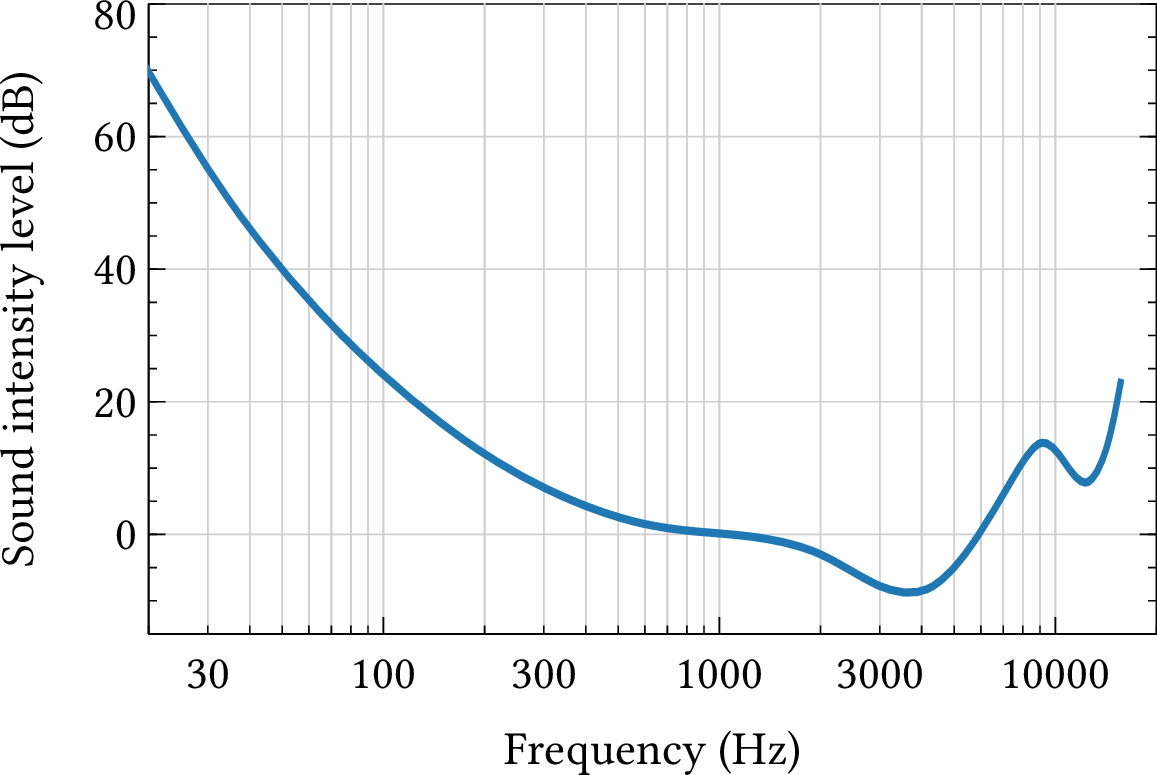
| PDF | PNG | 3.5 | Curve of constant apparent loudness
|
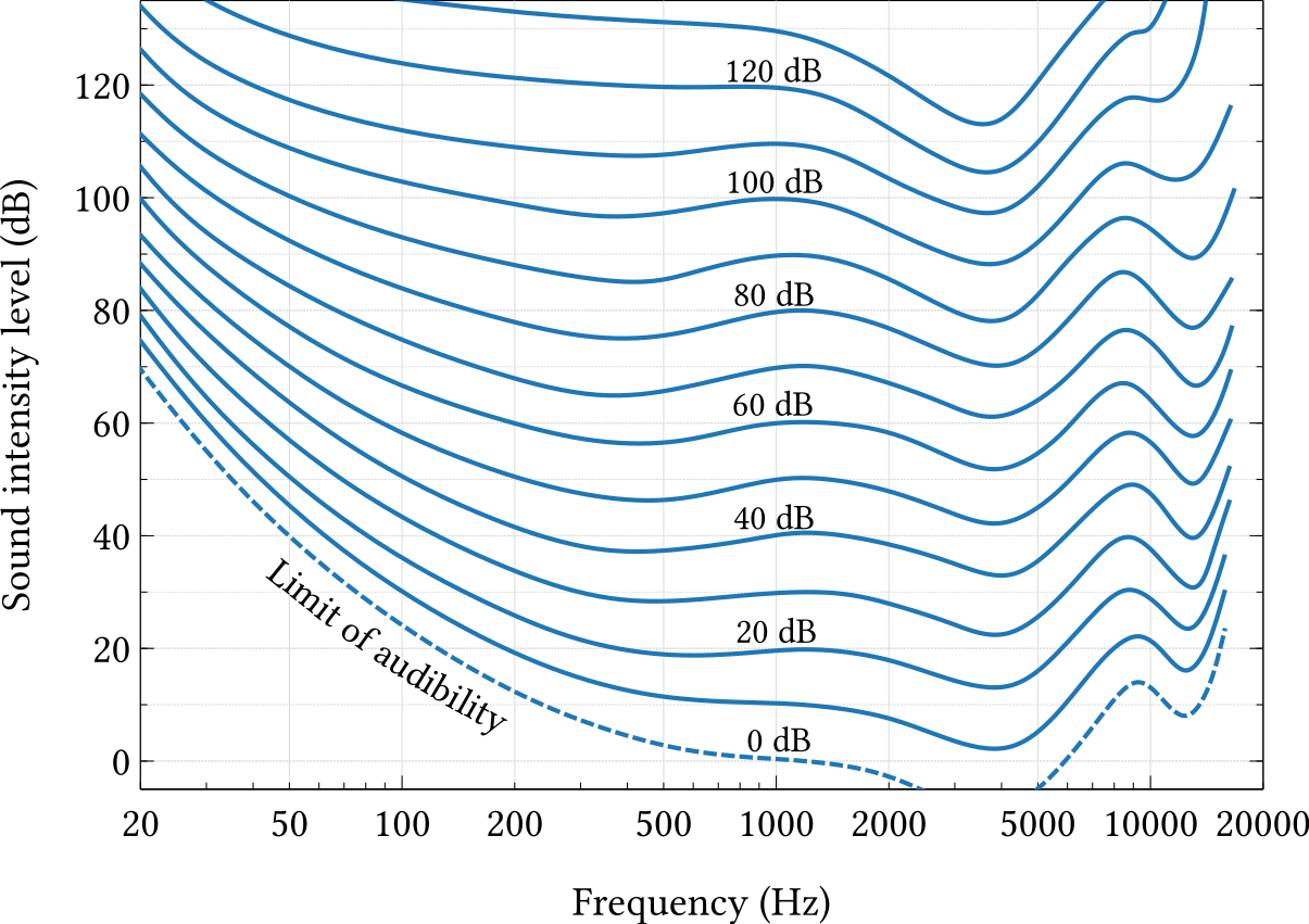
| PDF | PNG | 3.6 | Fletcher-Munson diagram
|
| JPEG | | – | Sound level meter
|
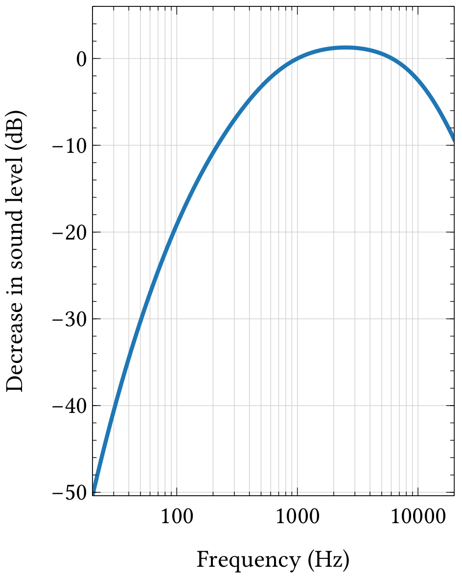
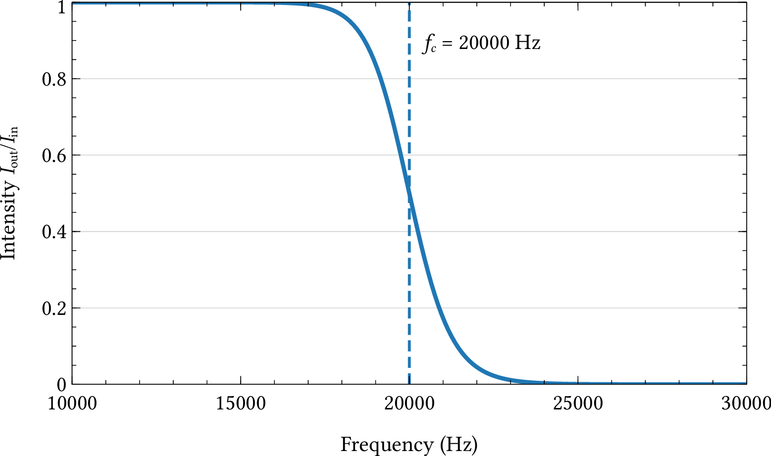
| PDF | PNG | 3.7 | Frequency response of a type-A filter
|
Chapter 4: Waveform and timbre
| Format | Figure | Description |
|---|
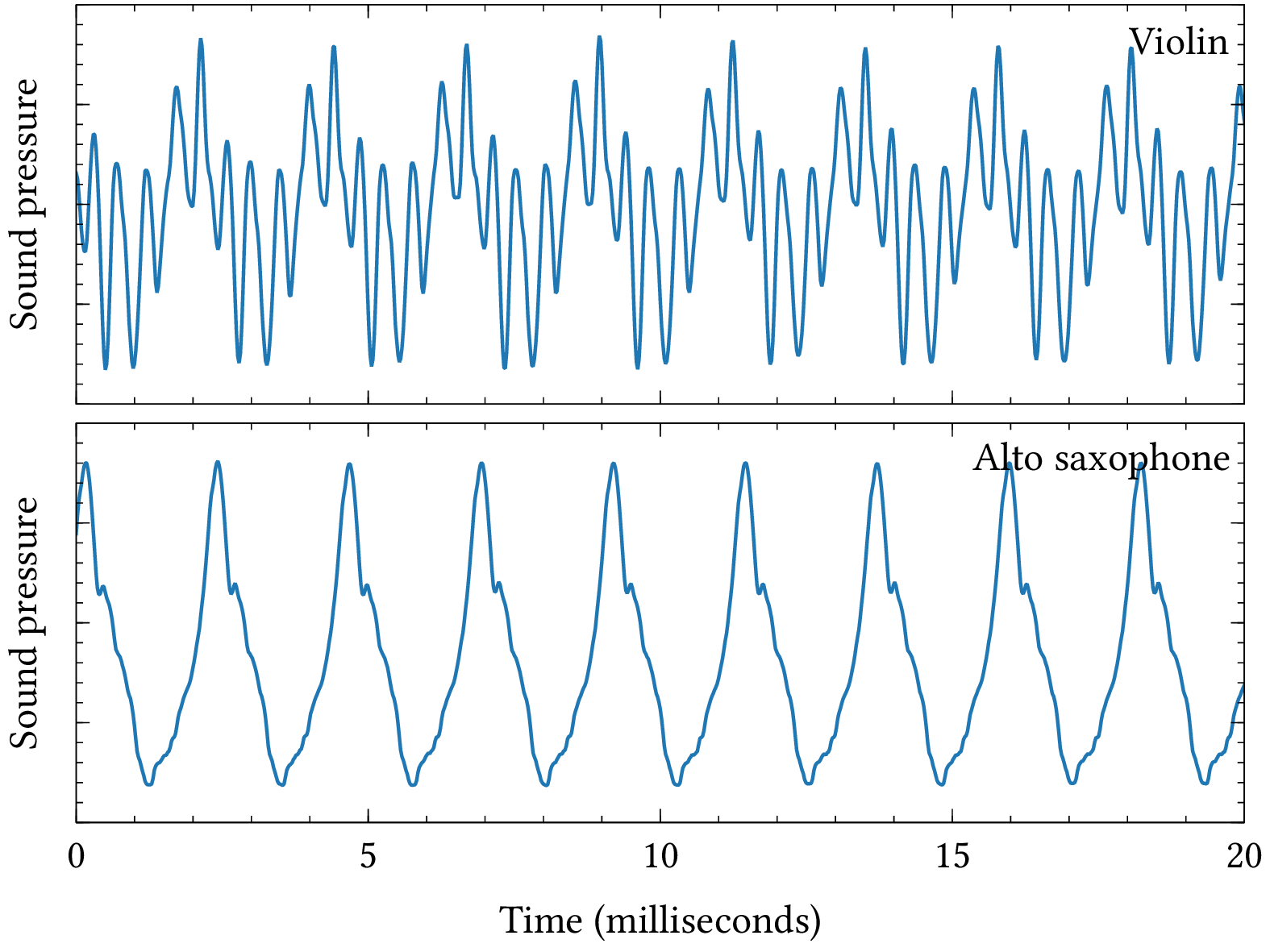
| PDF | PNG | 4.1 | Instrument waveforms
|
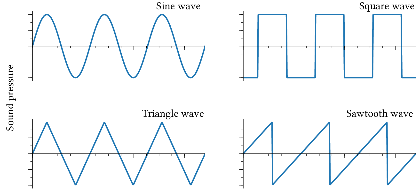
| PDF | PNG | 4.2 | Standard waveforms
|
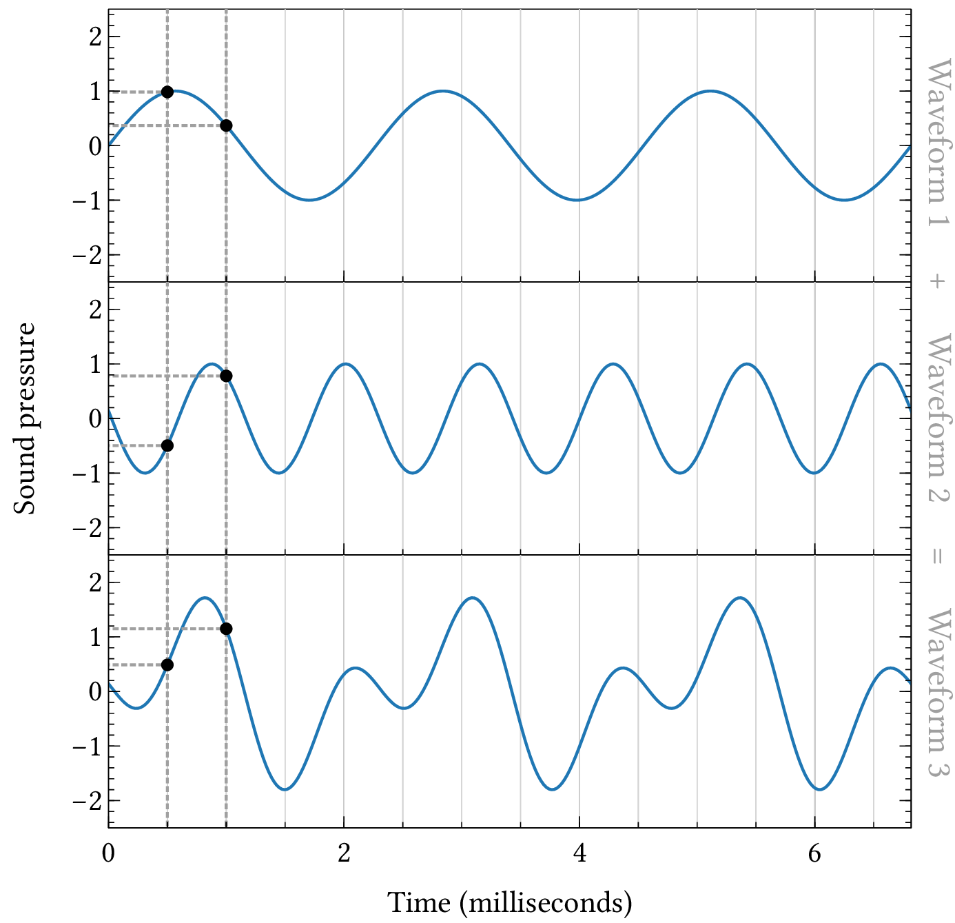
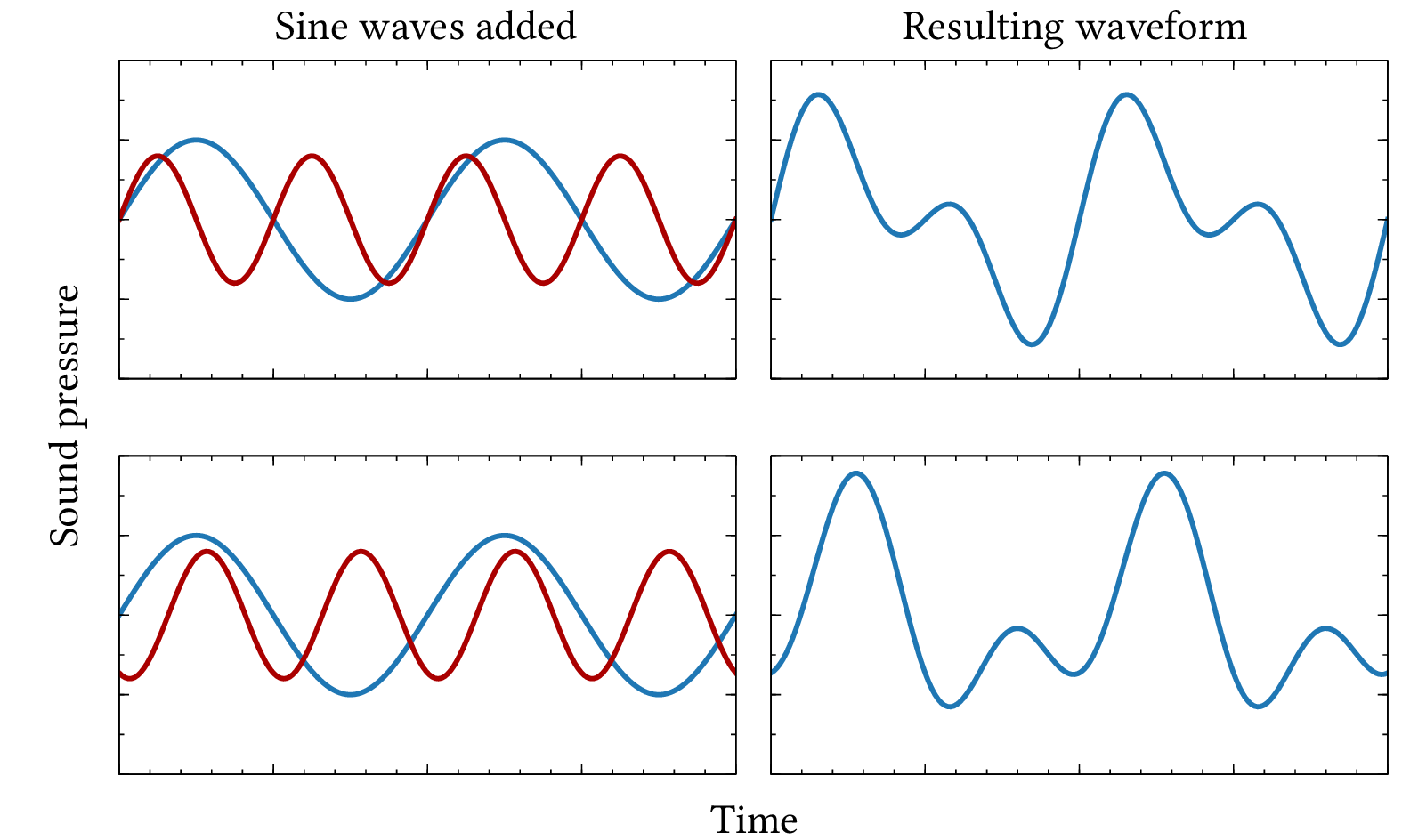
| PDF | PNG | 4.3 | Adding waveforms
|
| JPEG | | – | Mixer
|
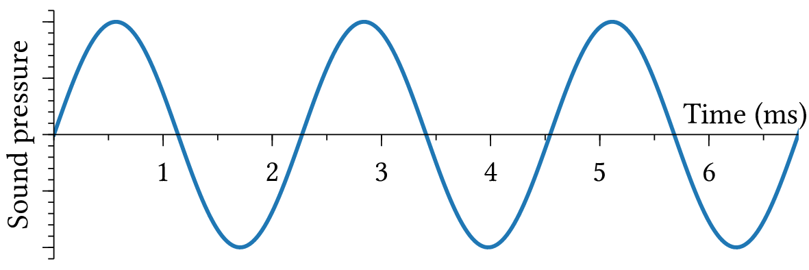
| PDF | PNG | 4.5 | Sine wave
|
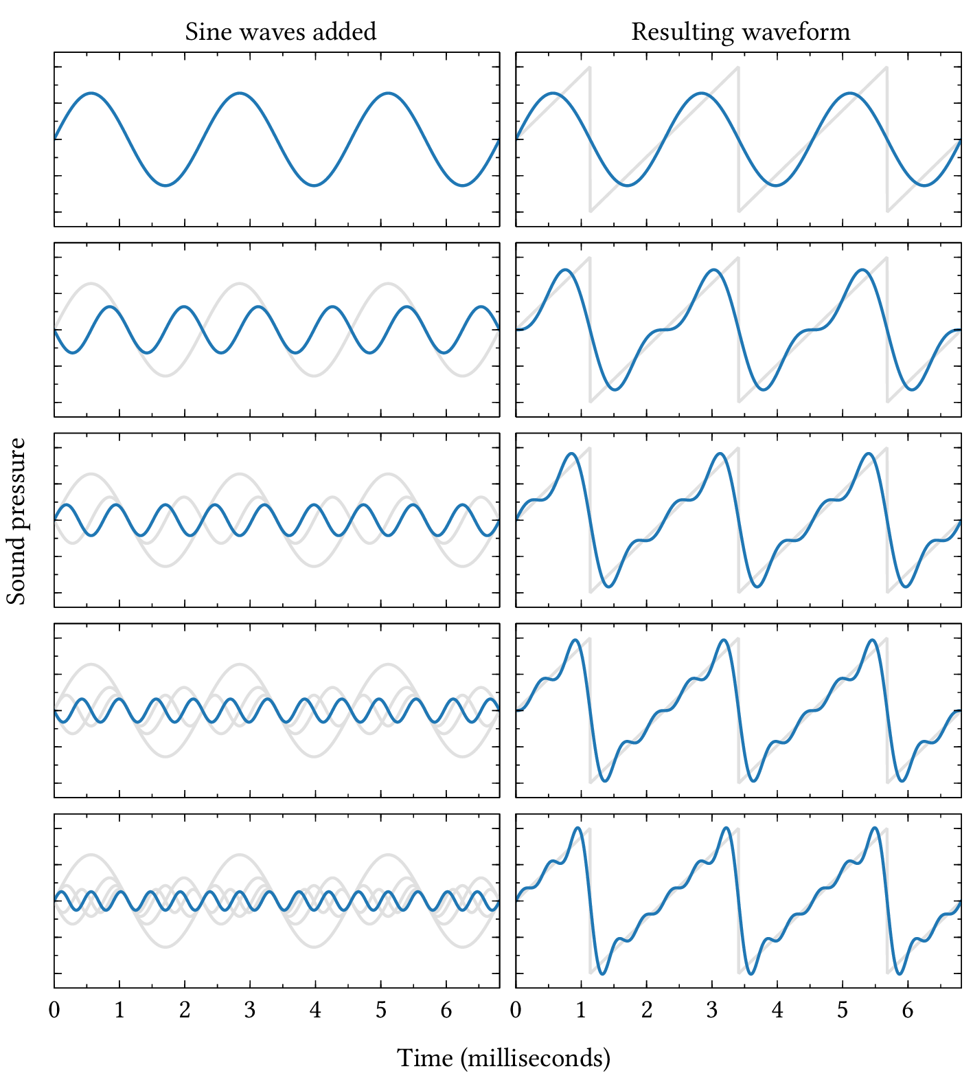
| PDF | PNG | 4.6 | Making a sawtooth wave
|
| PDF | PNG | – | Vase illusion
|
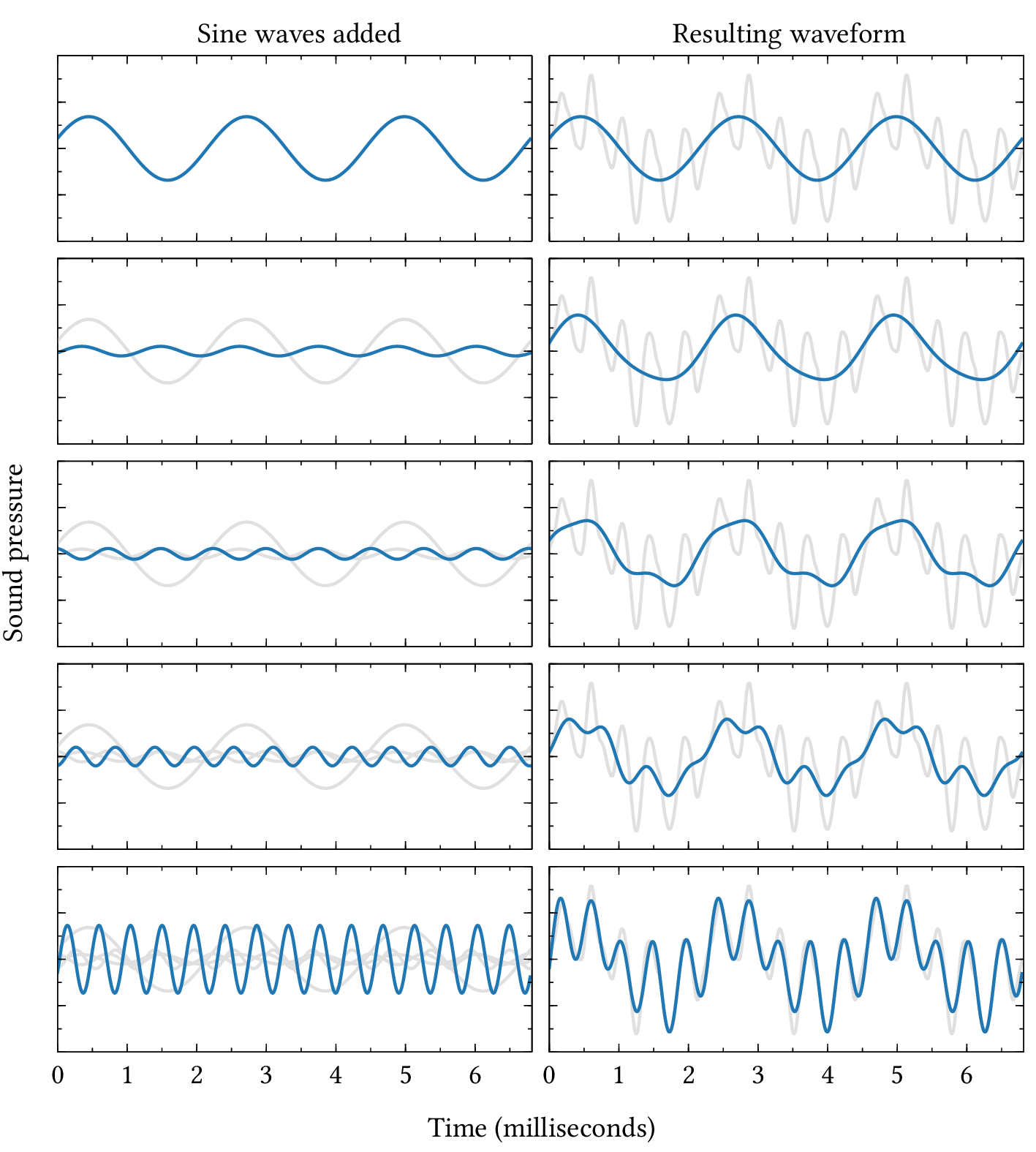
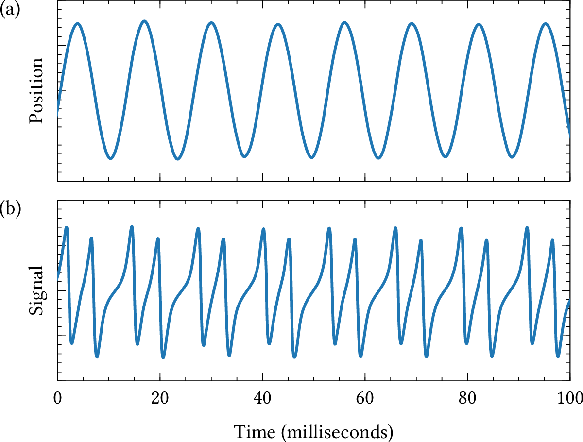
| PDF | PNG | 4.7 | Making a violin waveform
|
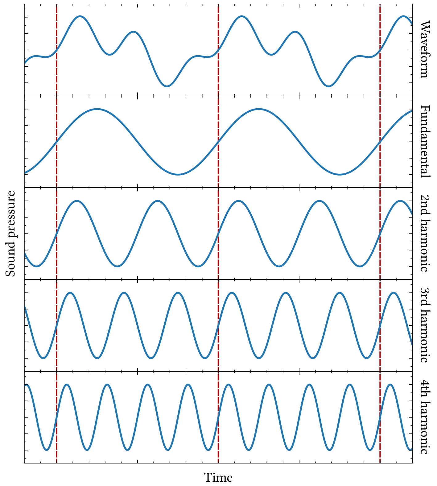
| PDF | PNG | 4.8 | Harmonics
|
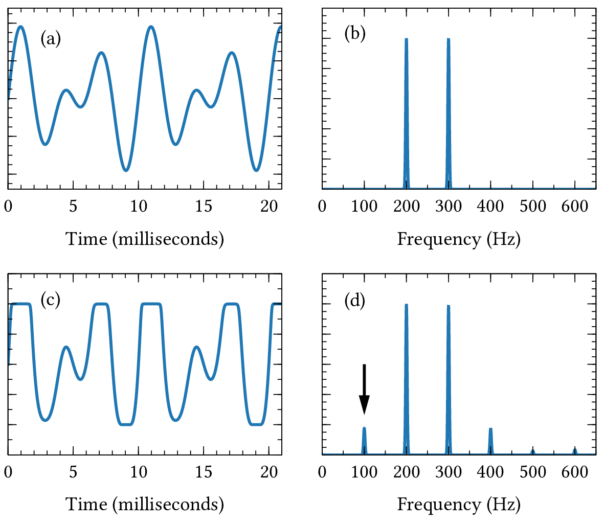
| PDF | PNG | – | Combination of sine waves (a)
|
| PDF | PNG | – | Combination of sine waves (b)
|
| PDF | PNG | – | Harmonic series
|
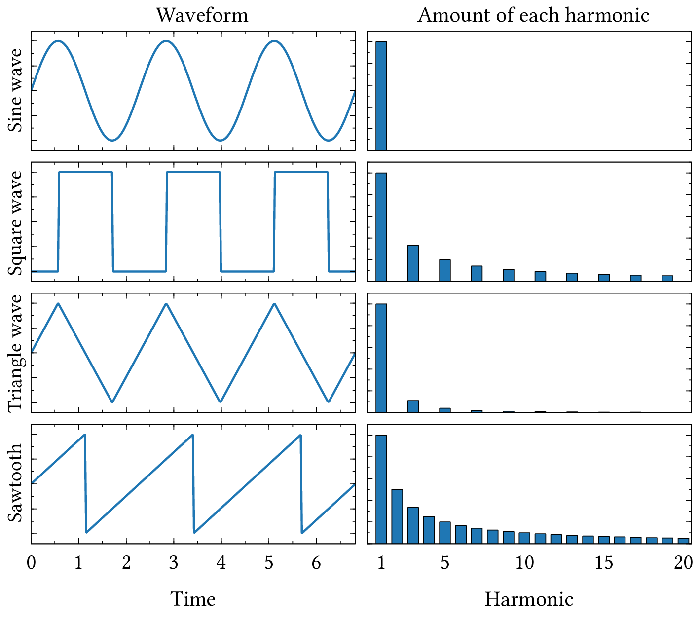
| PDF | PNG | 4.9 | Harmonics in standard waveforms
|
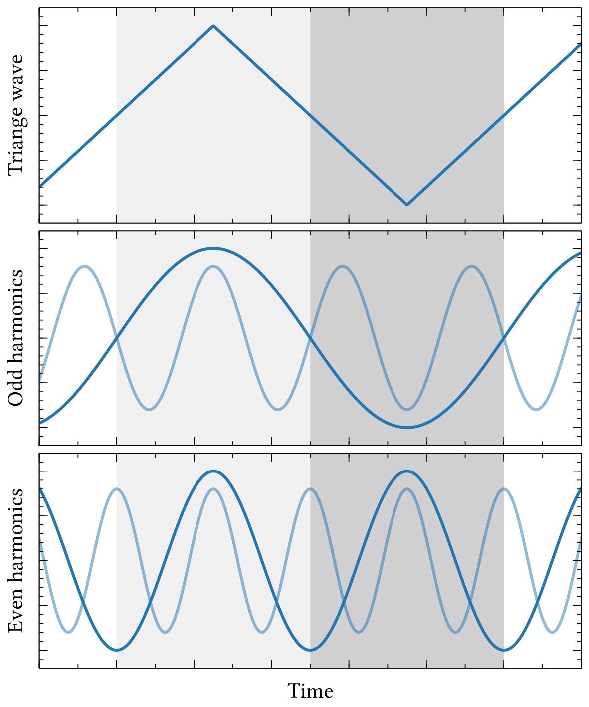
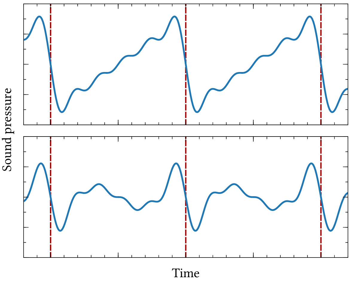
| PDF | PNG | 4.10 | Half-wave symmetry
|
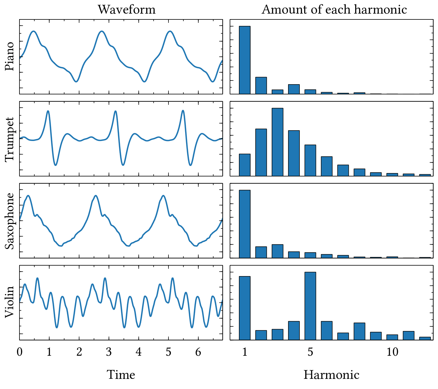
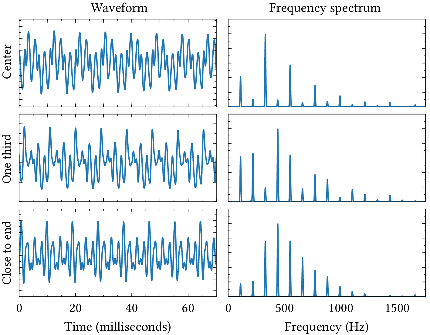
| PDF | PNG | 4.11 | Harmonics in instrument waveforms
|
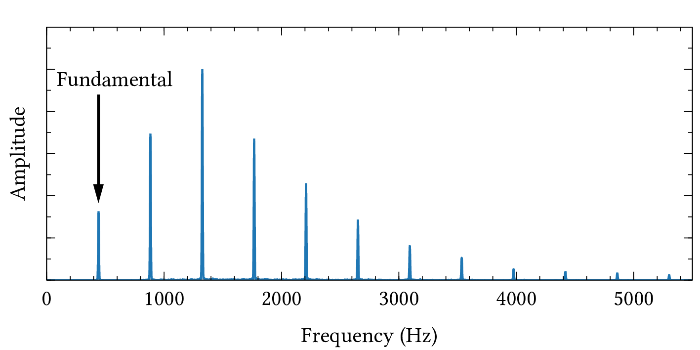
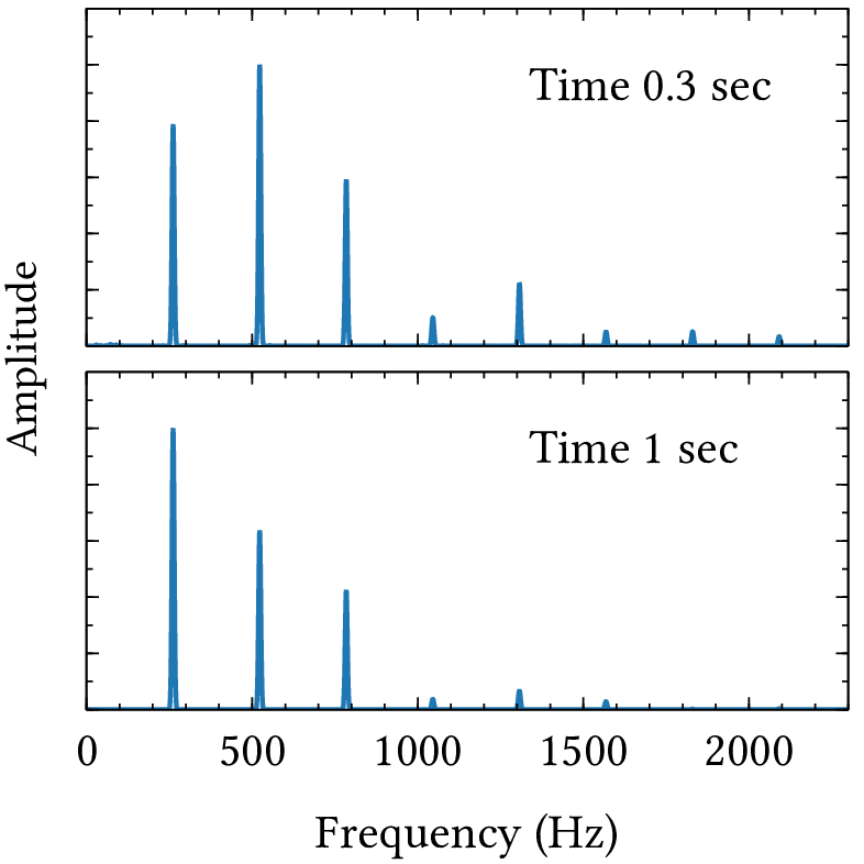
| PDF | PNG | 4.12 | Trumpet spectrum
|
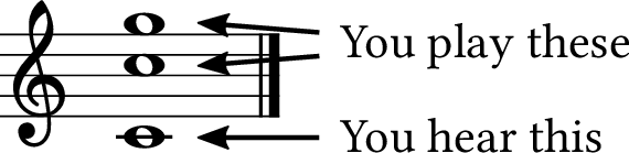
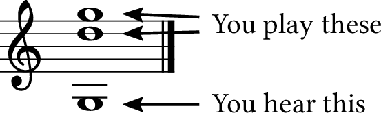
| PDF | PNG | 4.13 | Waveform with no fundamental
|
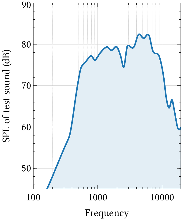
| PDF | PNG | 4.14 | Smartphone frequency response
|
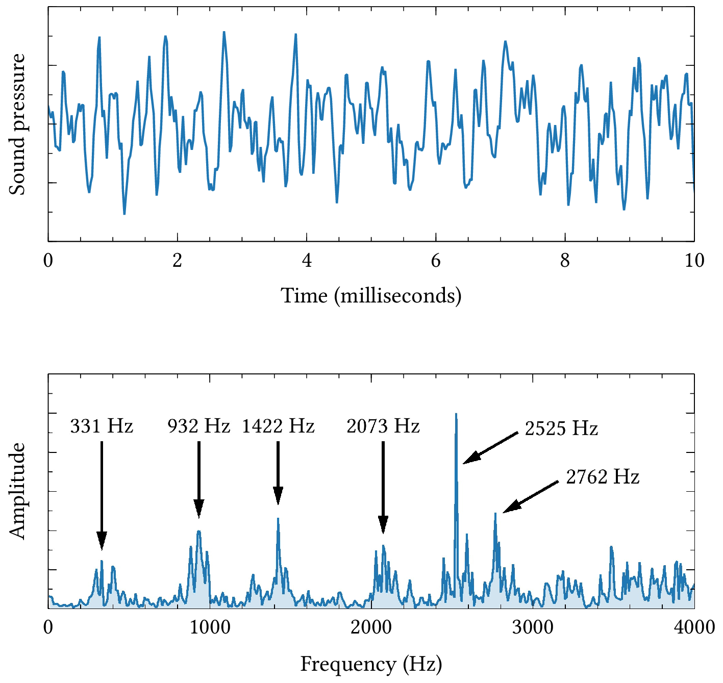
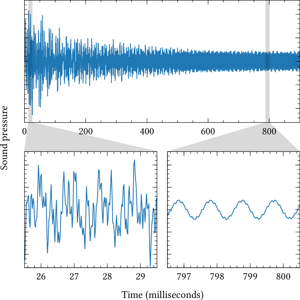
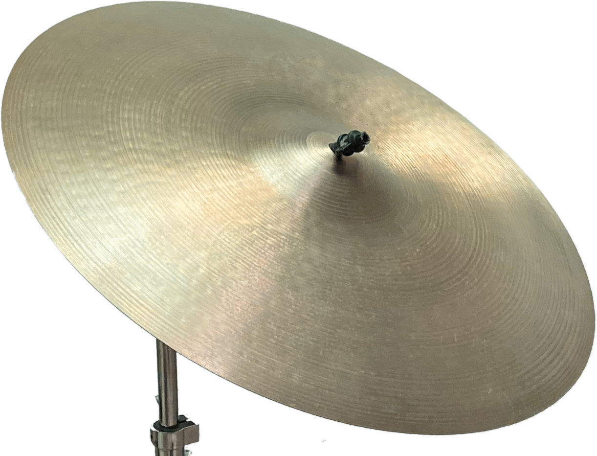
| PDF | PNG | 4.15 | Cymbal waveform and spectrum
|
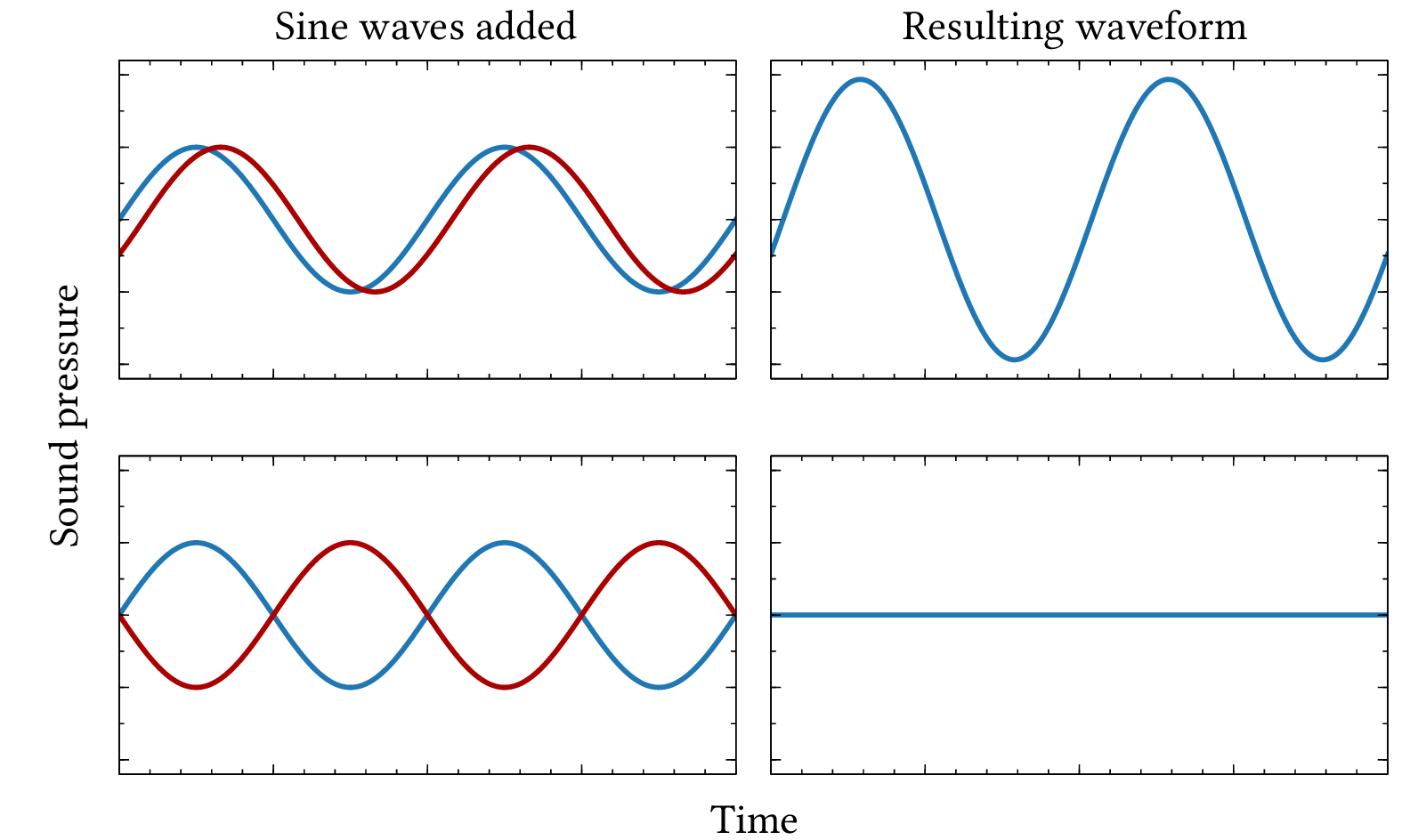
| PDF | PNG | 4.16 | Changing phase
|
| PDF | PNG | 4.17 | Phase cancellation
|
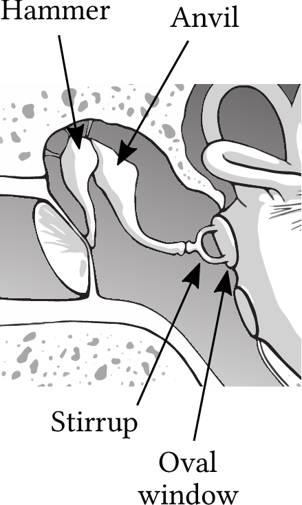
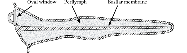
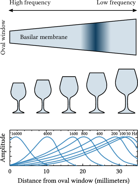
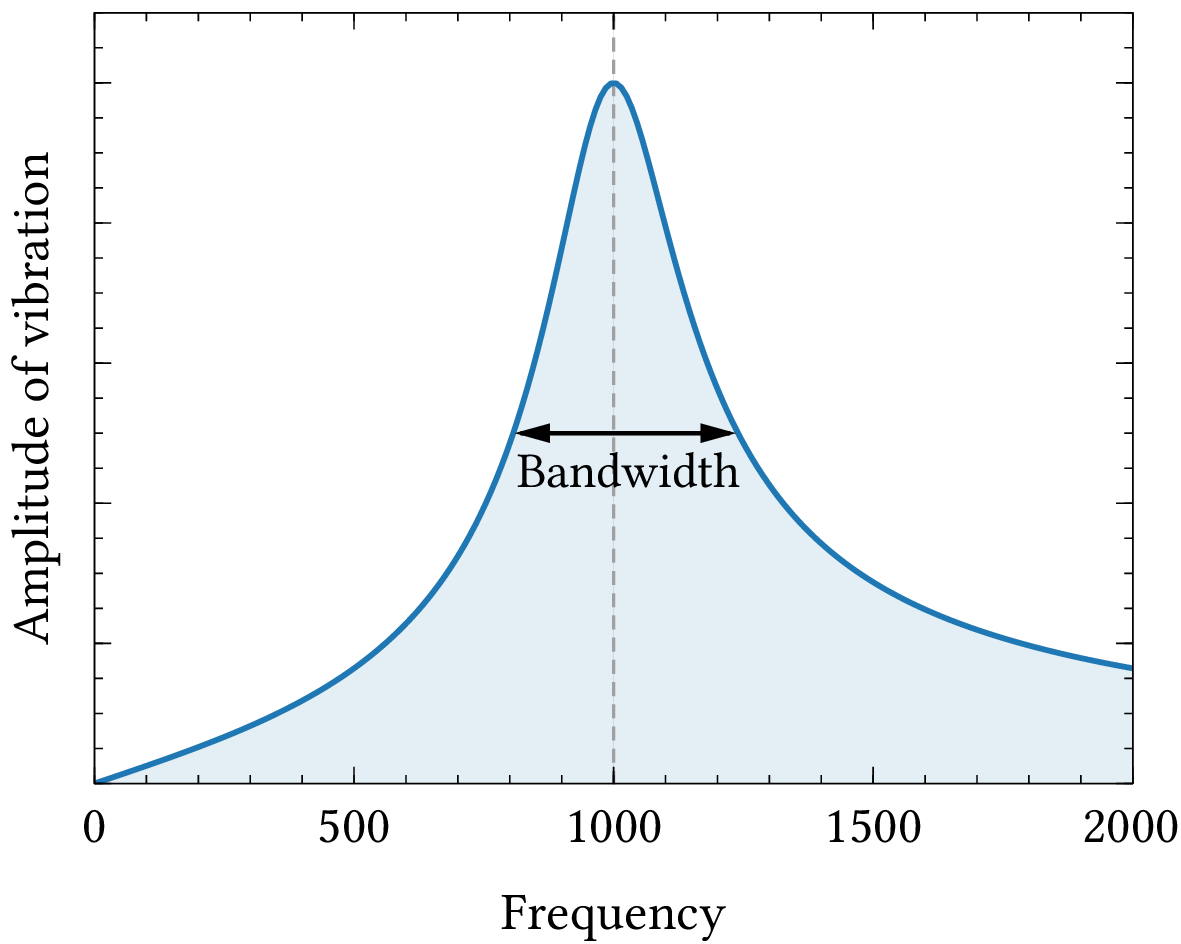
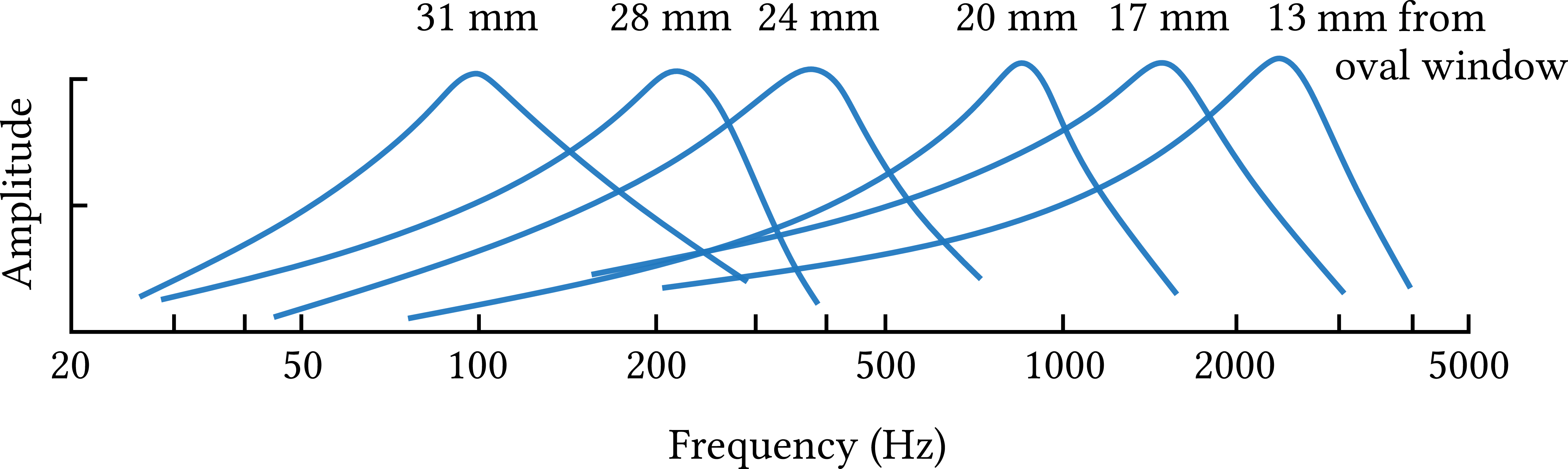
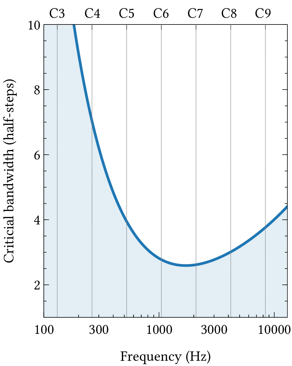
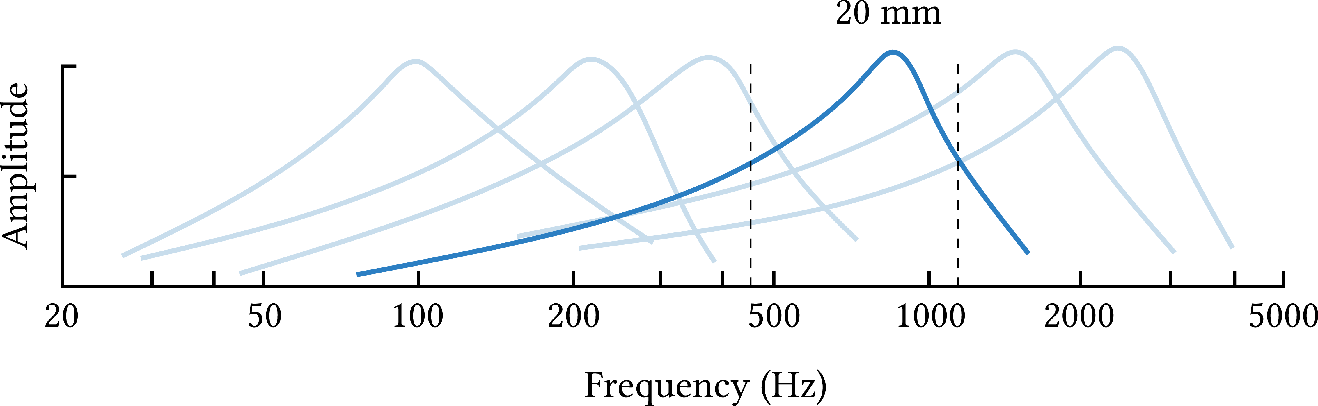
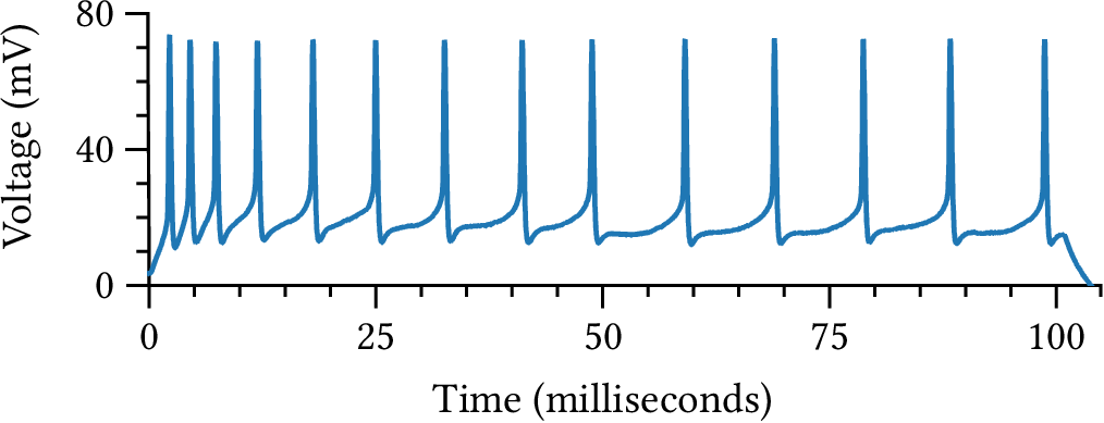
Chapter 5: Human hearing and the ear
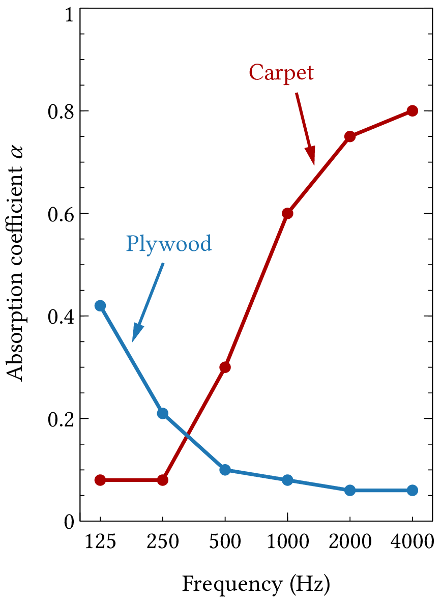
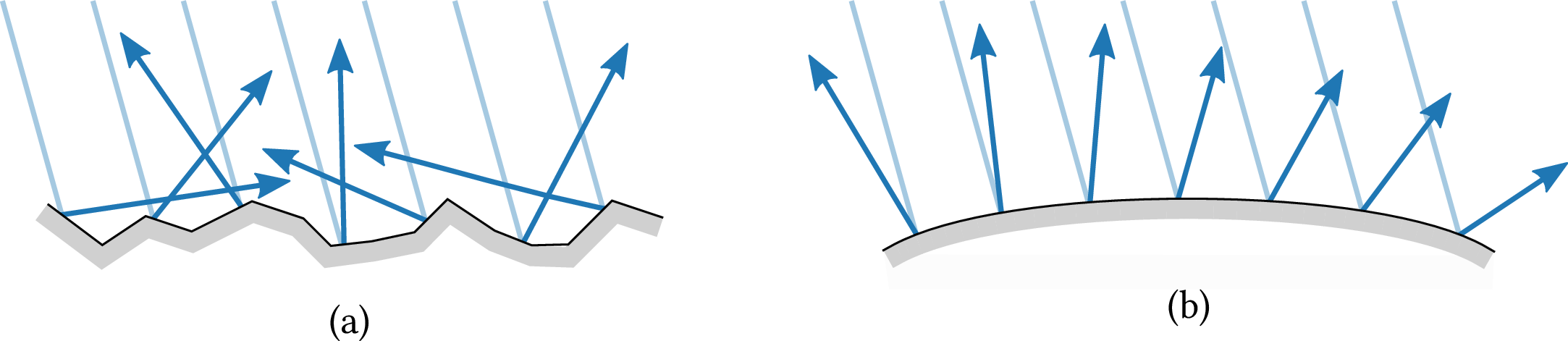
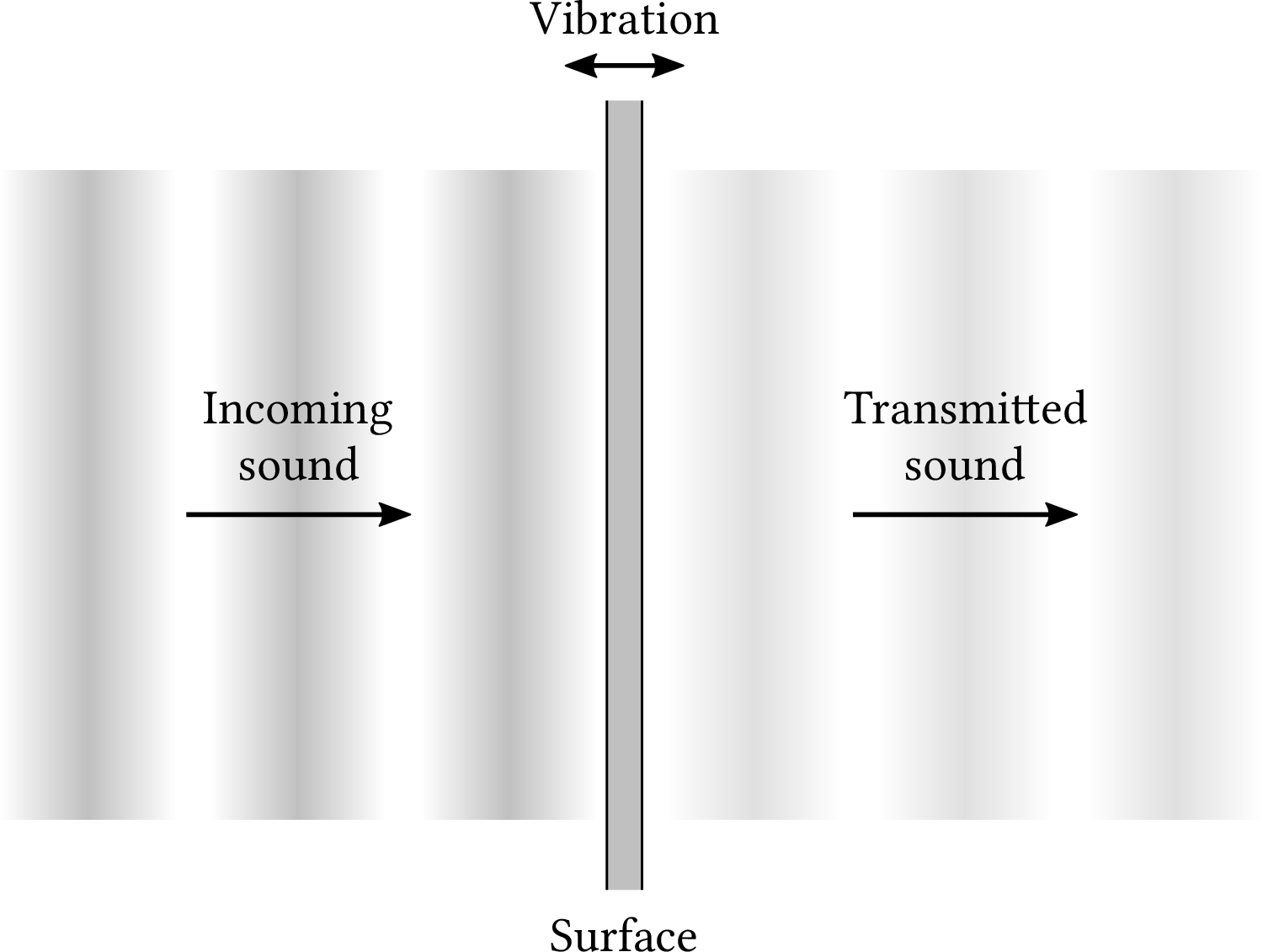
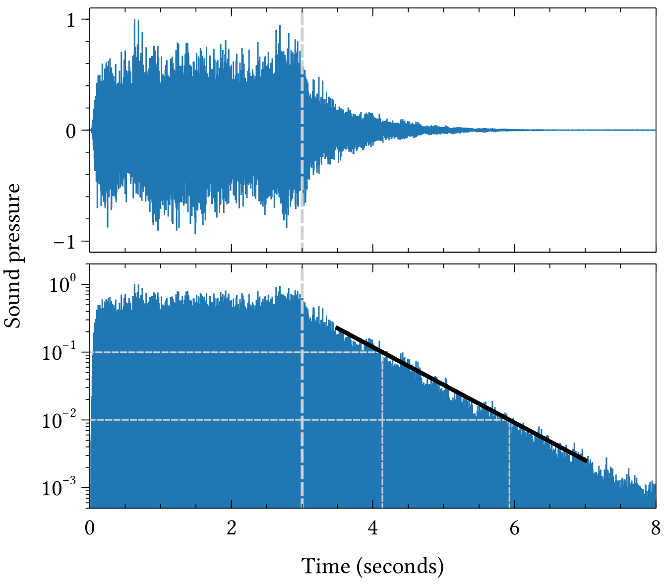
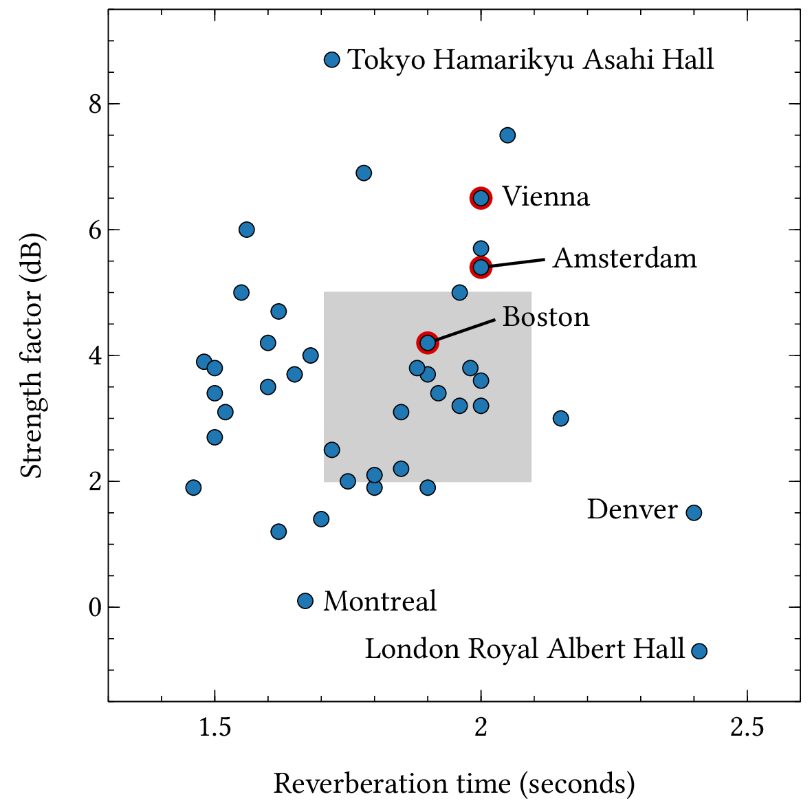
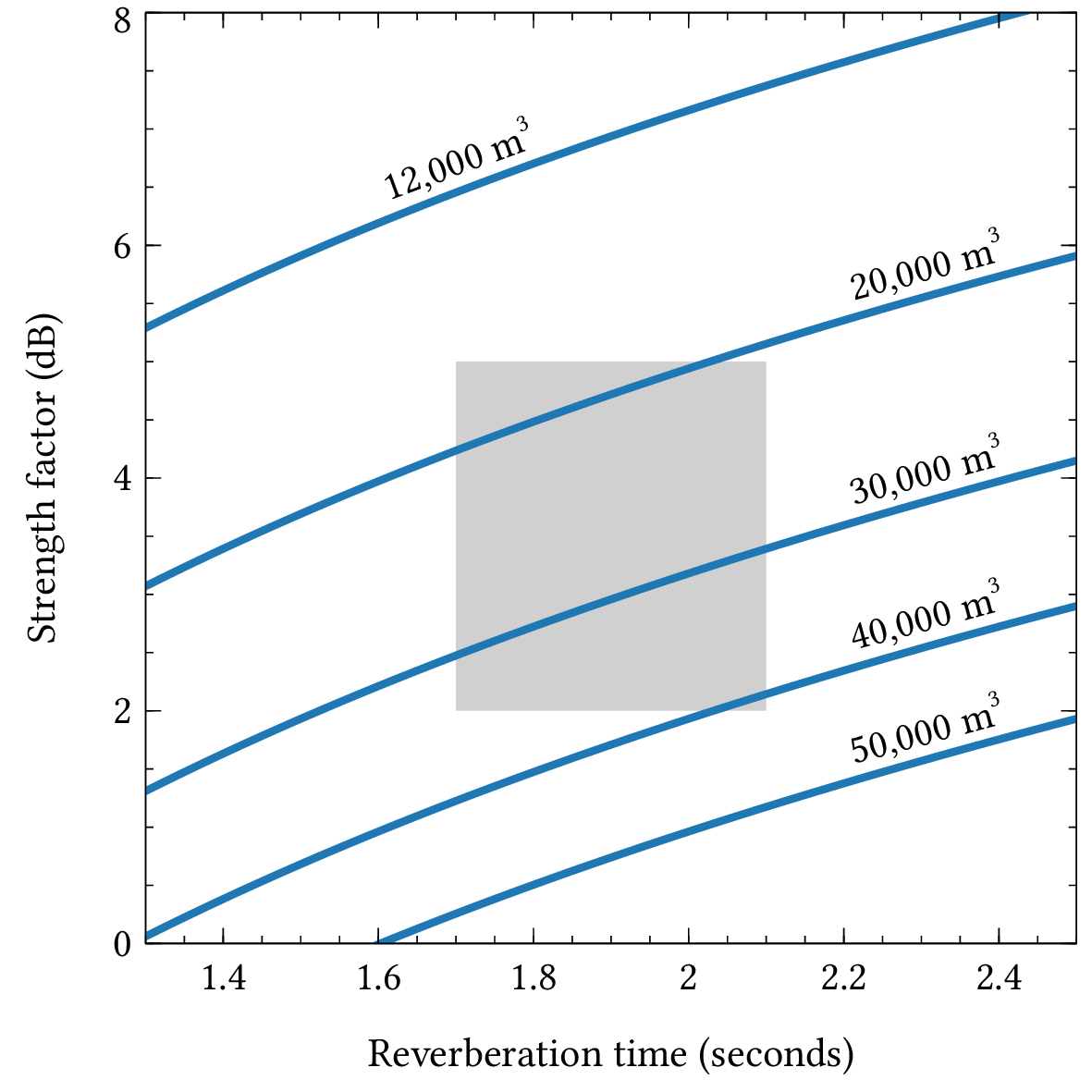
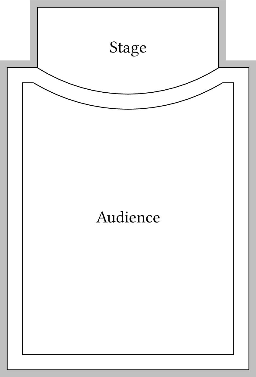
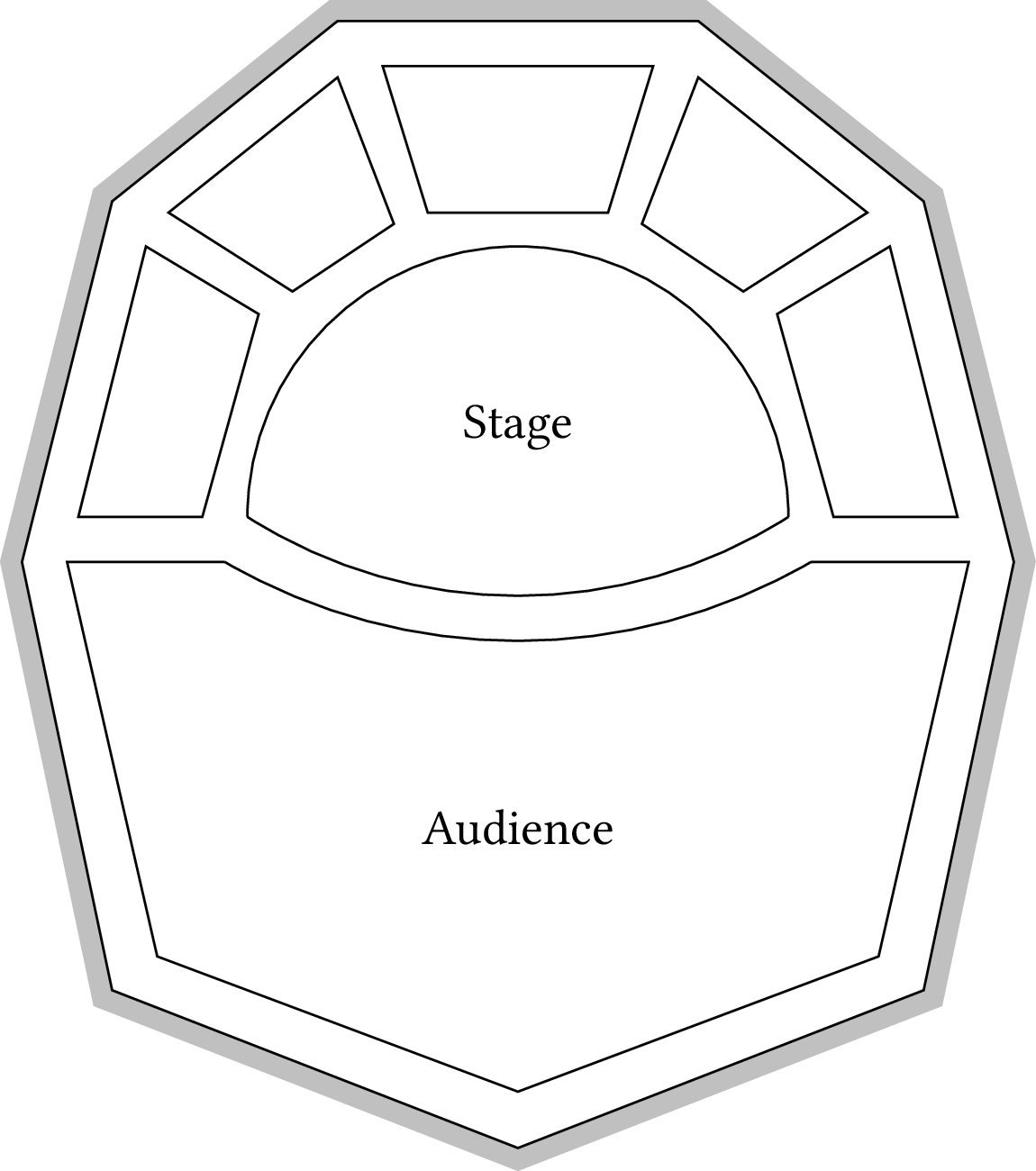
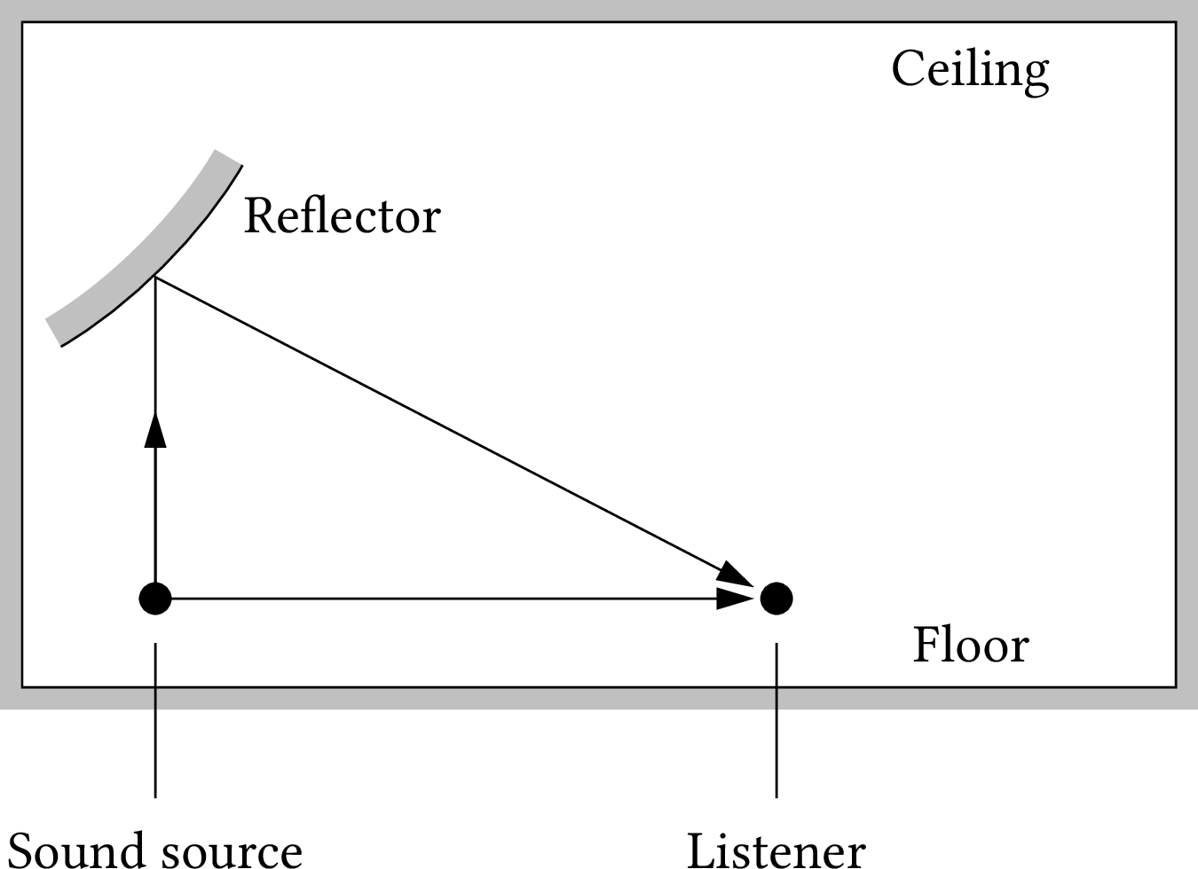
Chapter 6: Room acoustics
Chapter 7: Recording and reproduction
| Format | Figure | Description |
|---|
| PDF | PNG | 7.1 | The recording process
|
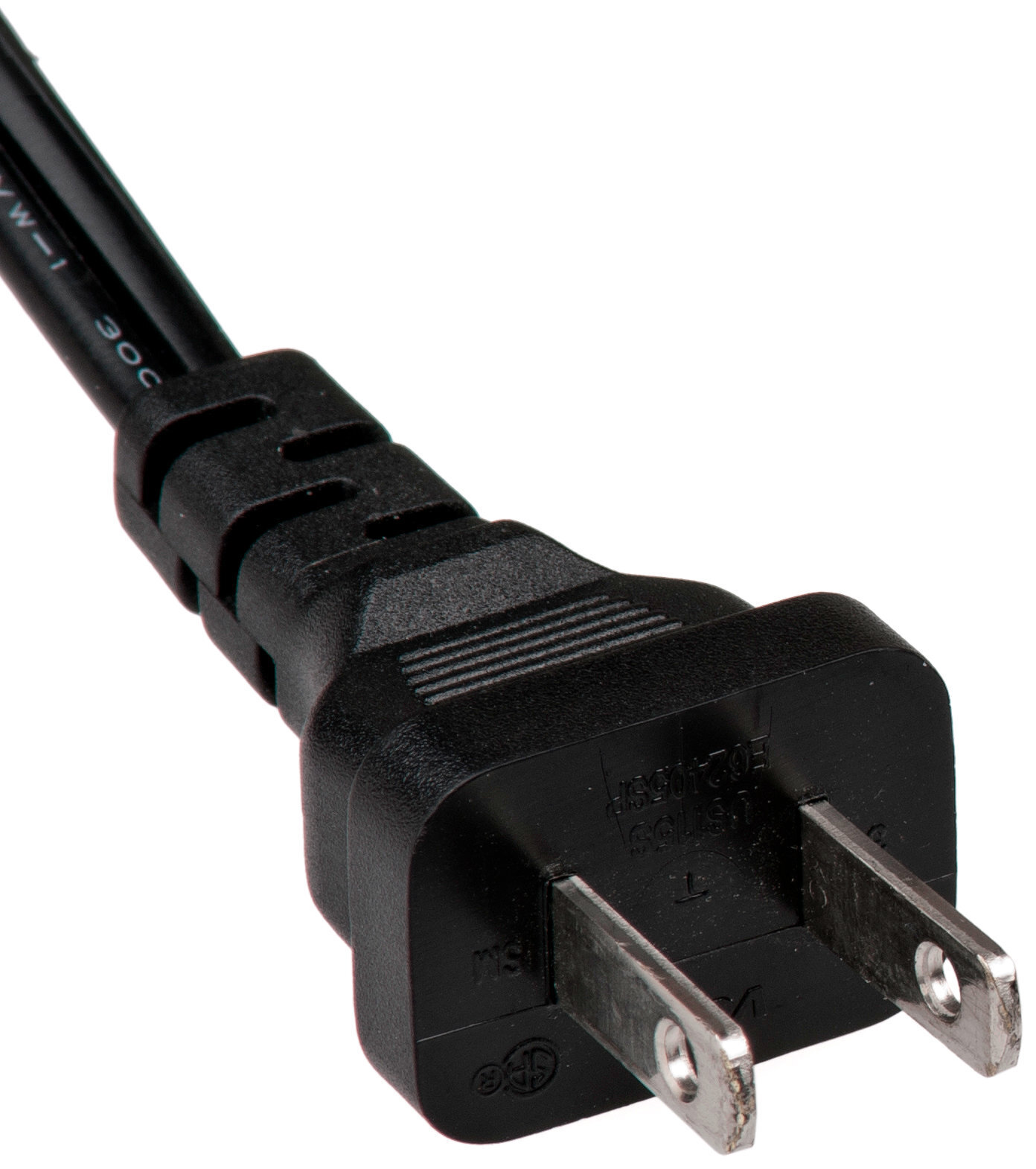
| JPEG | | – | Electrical plug
|
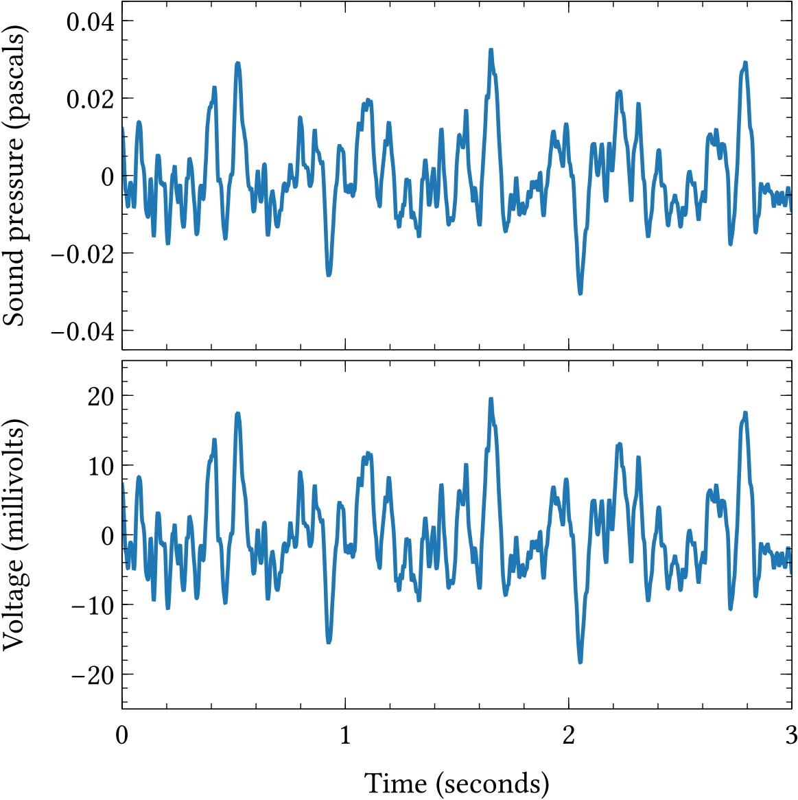
| PDF | PNG | 7.2 | Sound waveform as an electrical signal
|
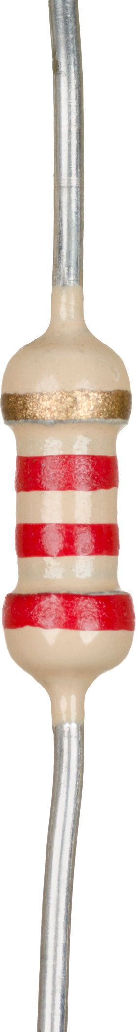
| JPEG | | – | Resistor
|
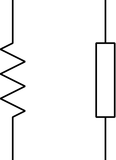
| PDF | PNG | – | Resistor symbols
|
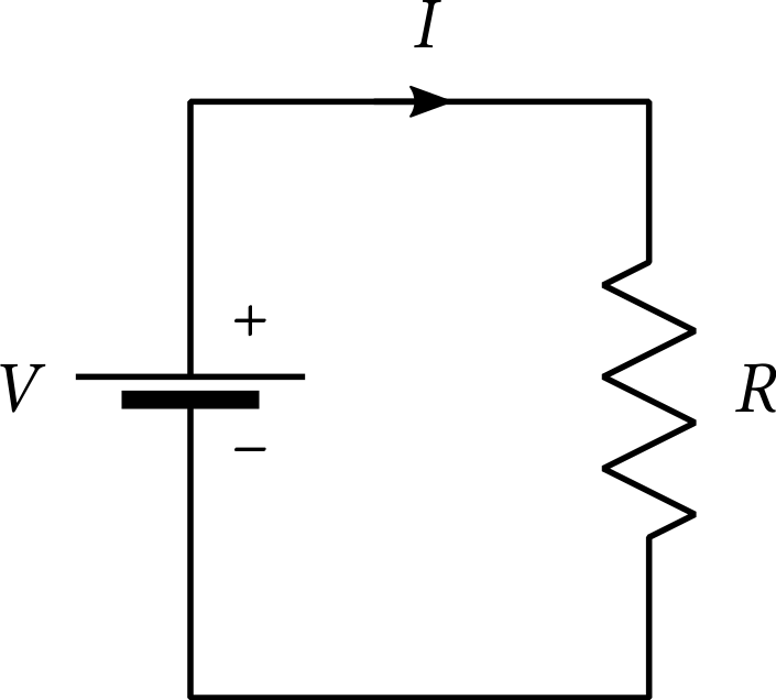
| PDF | PNG | 7.3 | A simple circuit
|
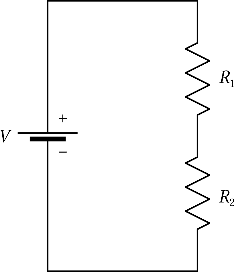
| PDF | PNG | 7.4 | A circuit with two resistors
|
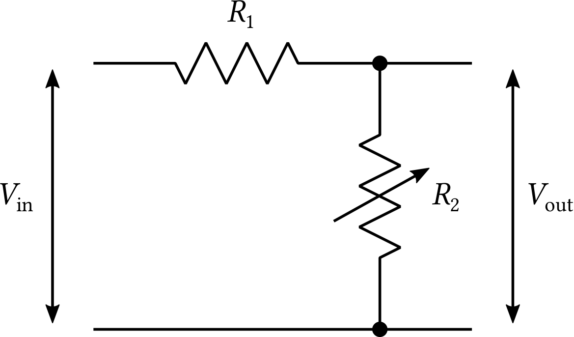
| PDF | PNG | 7.5 | Volume control
|
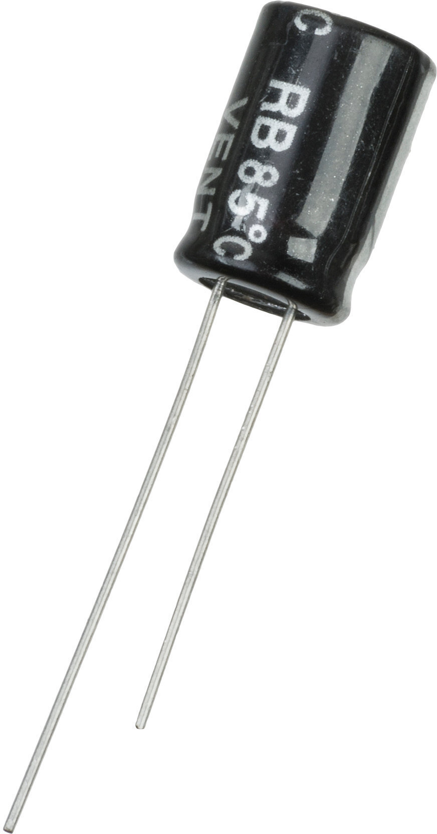
| JPEG | | – | Capacitor
|
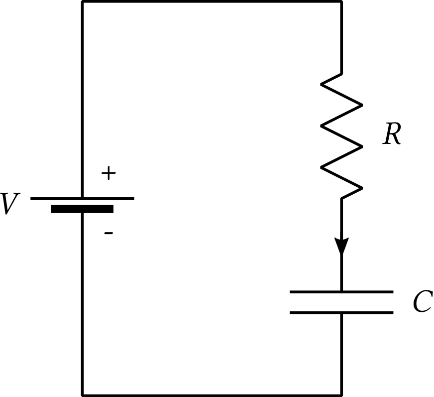
| PDF | PNG | 7.6 | A circuit using a capacitor
|
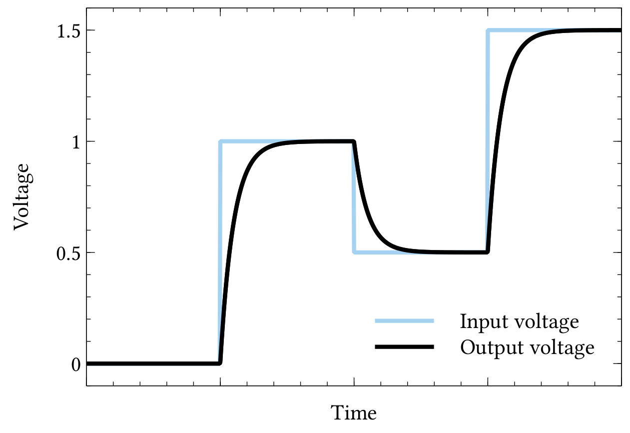
| PDF | PNG | 7.7 | The effect of the circuit in Fig. 7.6
|
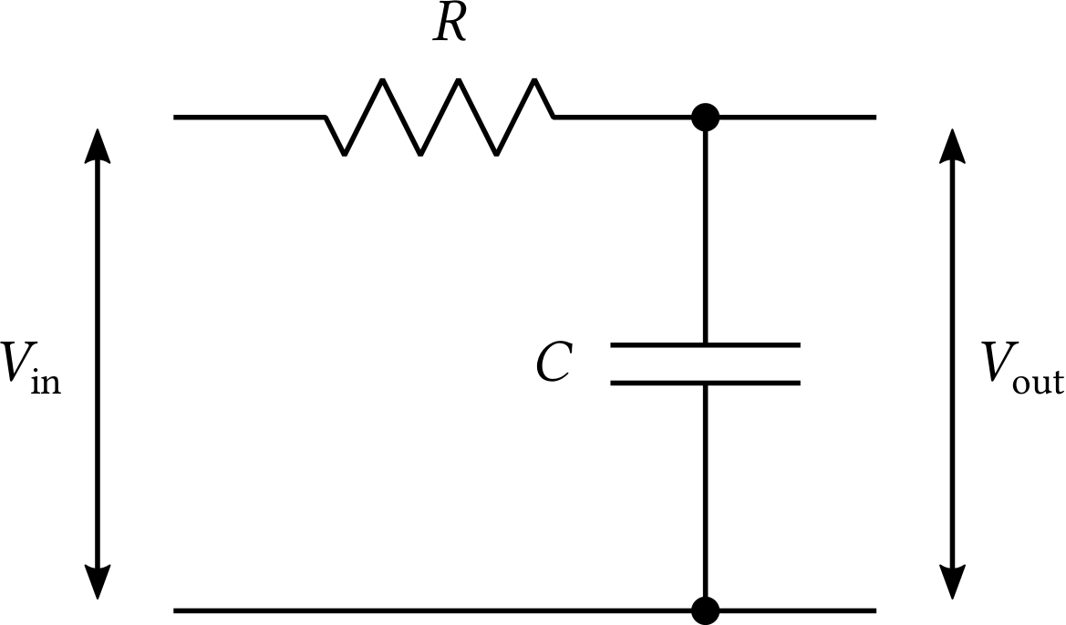
| PDF | PNG | 7.8 | A low-pass filter
|
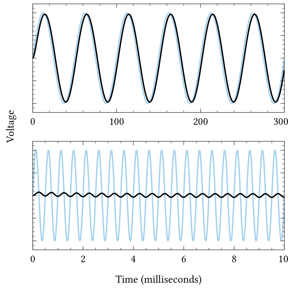
| PDF | PNG | 7.9 | The effect of the low-pass filter
|
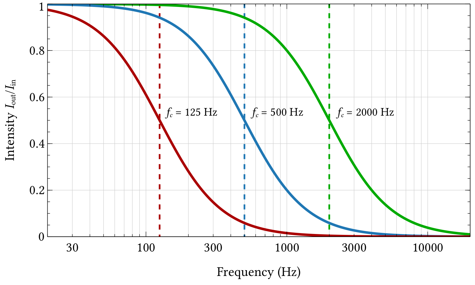
| PDF | PNG | 7.10 | Frequency response of the low-pass filter
|
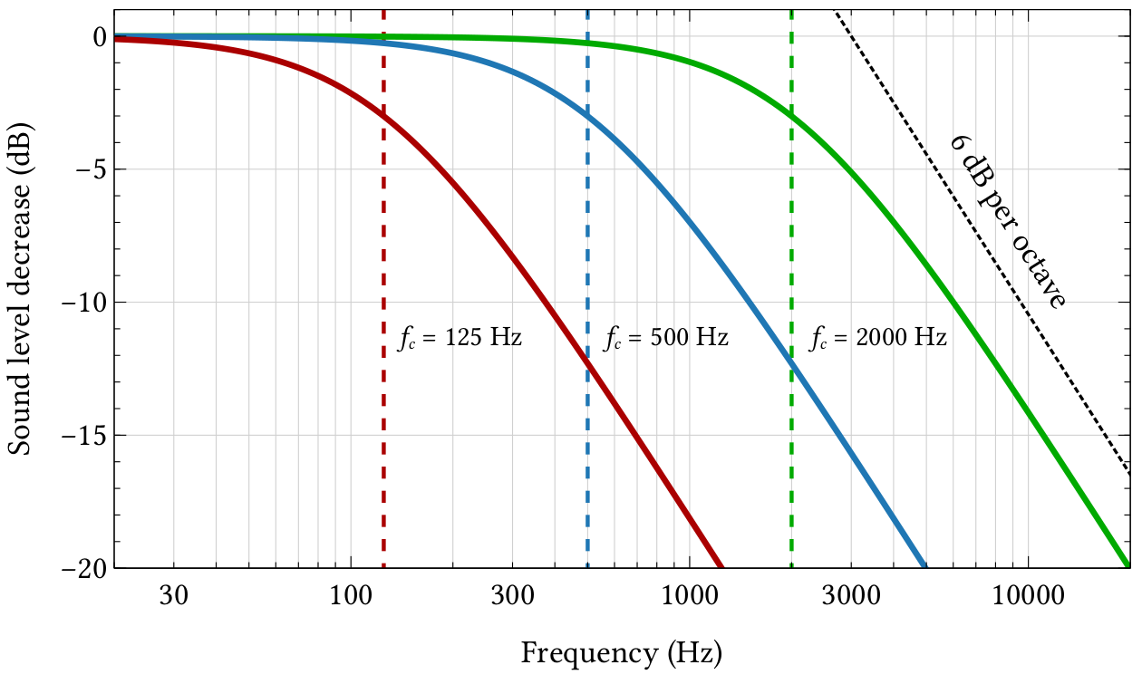
| PDF | PNG | 7.11 | Sound level decrease upon applying the low-pass filter
|
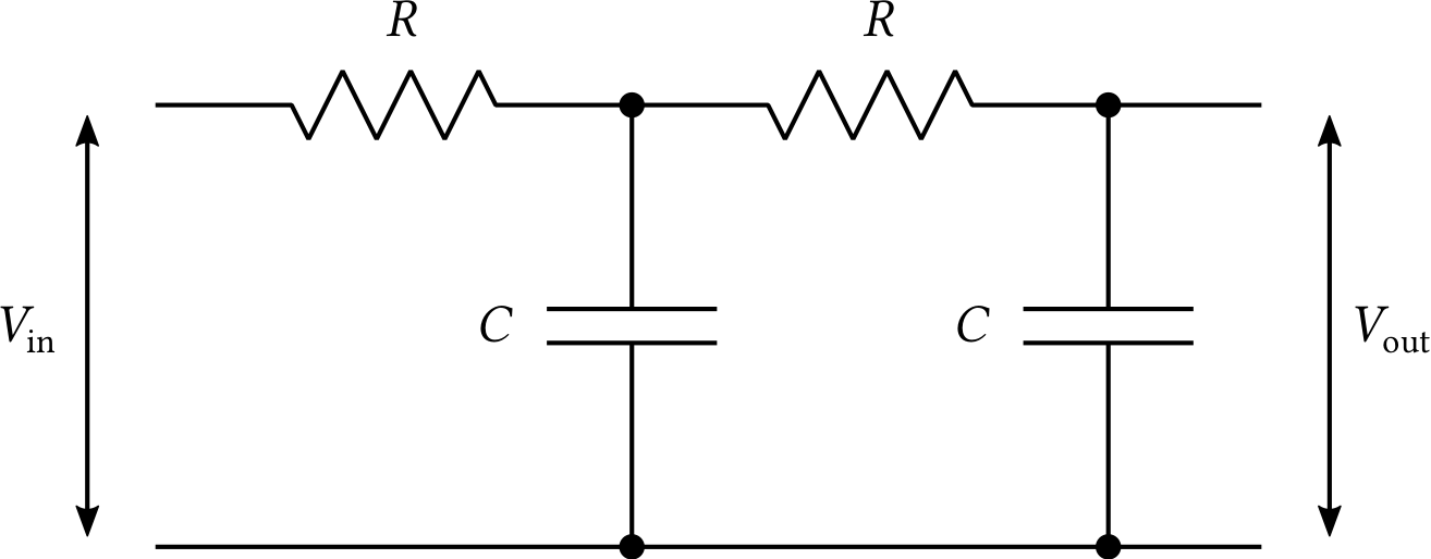
| PDF | PNG | 7.12 | A 12 dB-per-octave low-pass filter
|
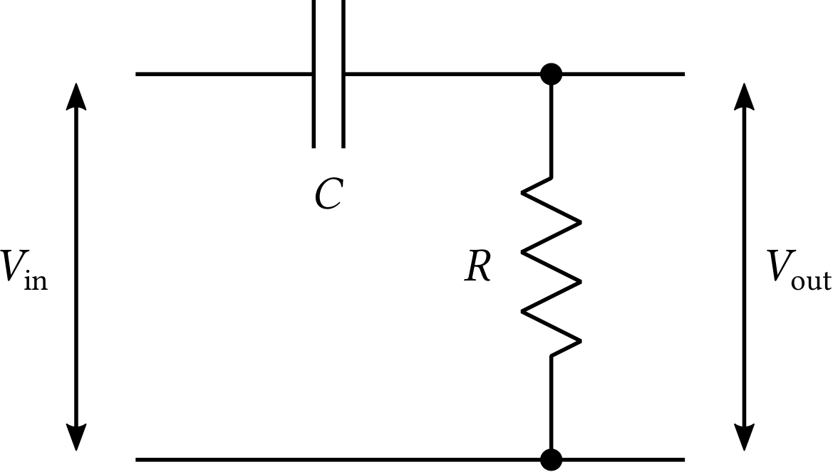
| PDF | PNG | 7.13 | A high-pass filter
|
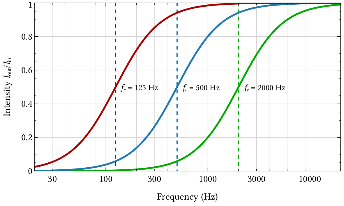
| PDF | PNG | 7.14 | Frequency response of the high-pass filter
|
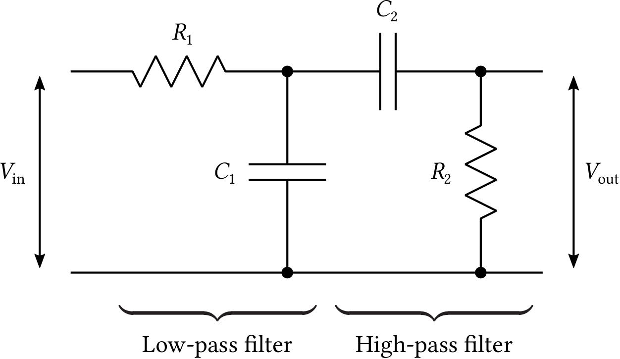
| PDF | PNG | 7.15 | A band-pass filter
|
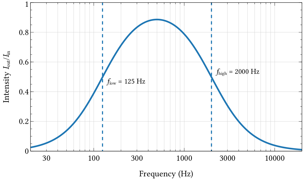
| PDF | PNG | 7.16 | Frequency response of a band-pass filter
|
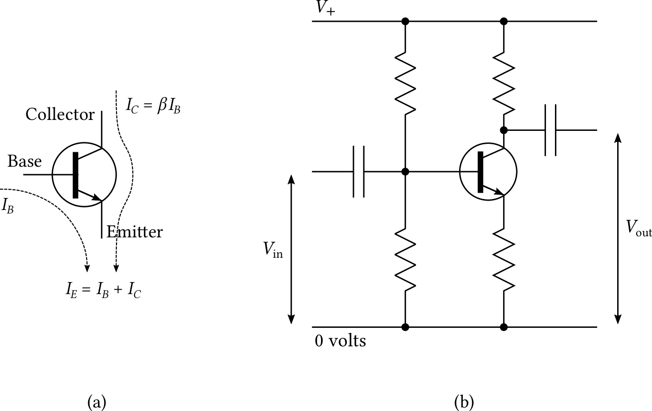
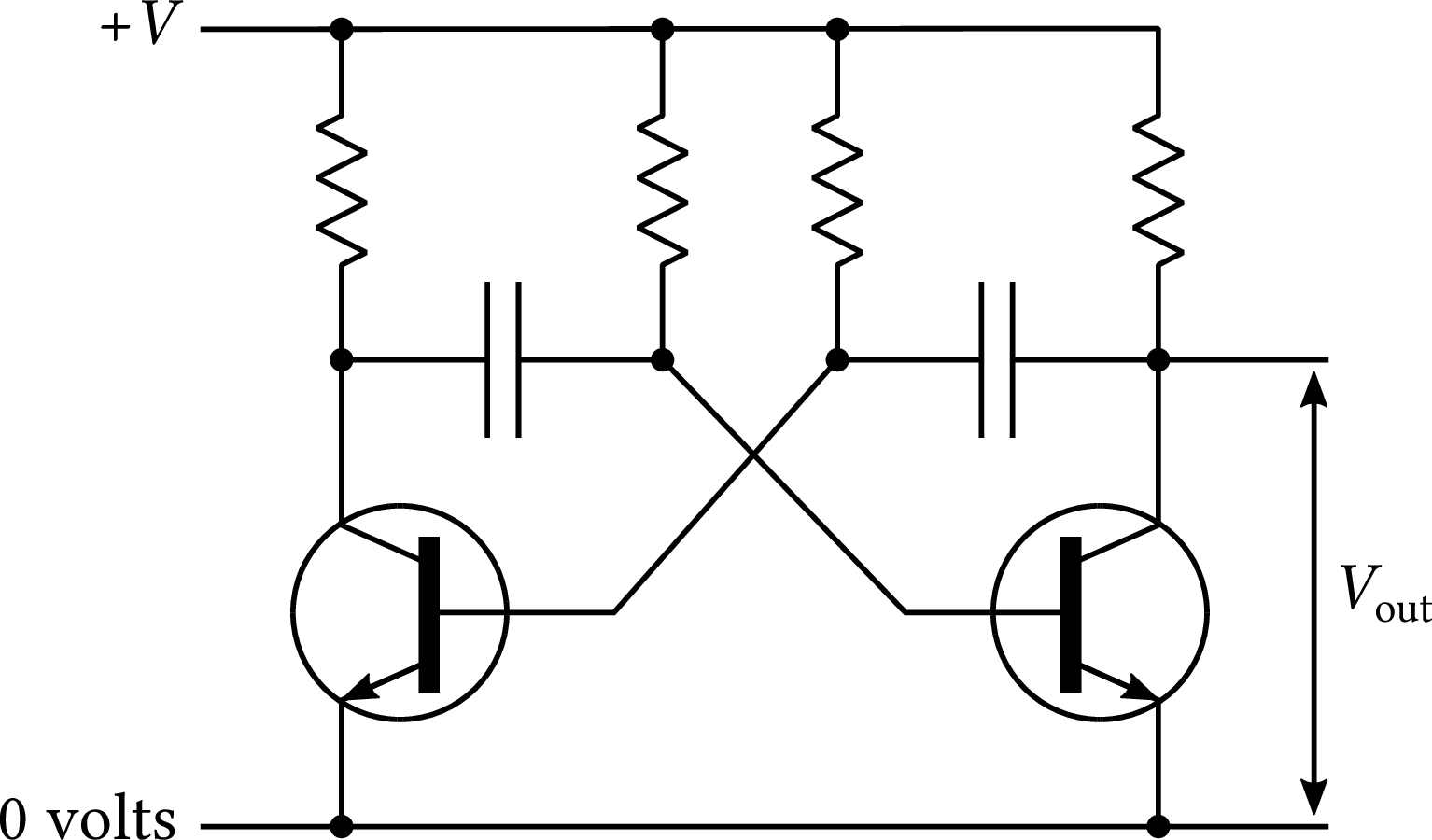
| PDF | PNG | 7.17 | Transistor circuits
|
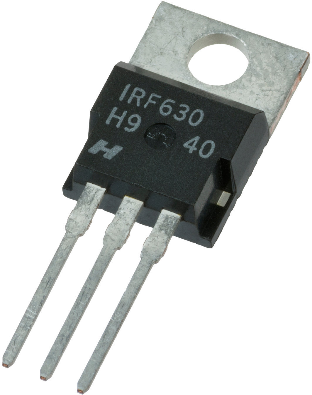
| JPEG | | – | Transistor
|
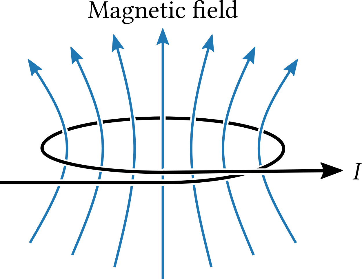
| PDF | PNG | 7.18 | A loop of wire
|
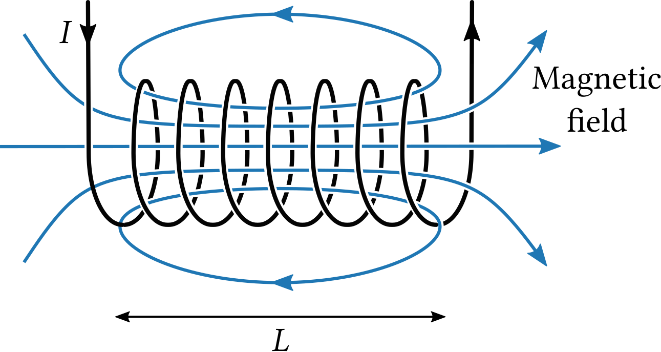
| PDF | PNG | 7.19 | A solenoid
|
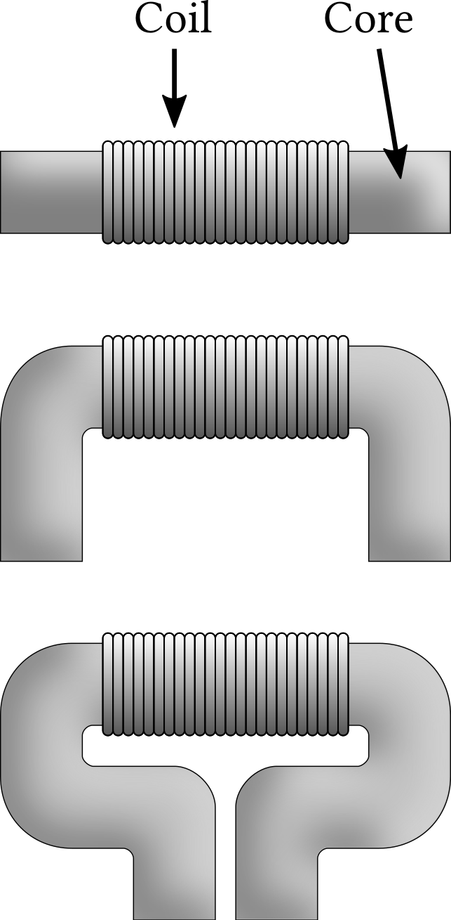
| PDF | PNG | 7.20 | The core of a solenoid
|
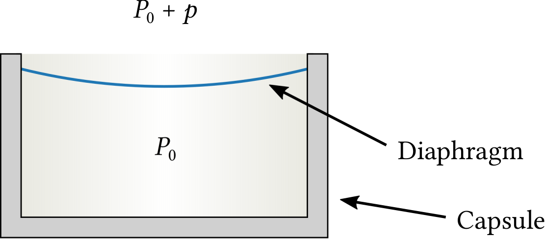
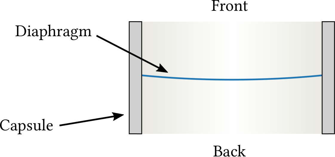
| PDF | PNG | 7.21 | Pressure microphone
|
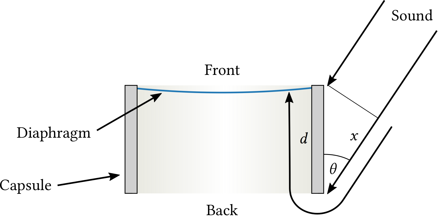
| PDF | PNG | 7.22 | Pressure-gradient microphone
|
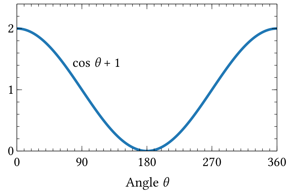
| PDF | PNG | 7.23 | Effective sound pressure measured by a cardioid microphone
|
| PDF | PNG | 7.24 | Bidirectional microphone
|
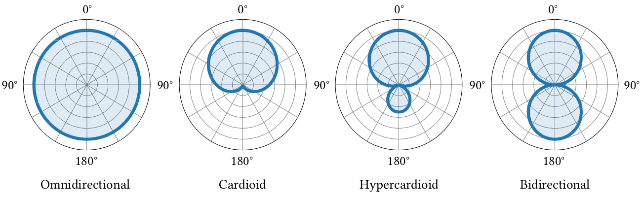
| PDF | PNG | 7.25 | Polar plots
|
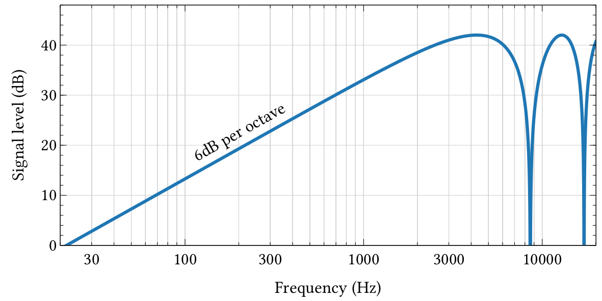
| PDF | PNG | 7.26 | Frequency response of a pressure-gradient microphone
|
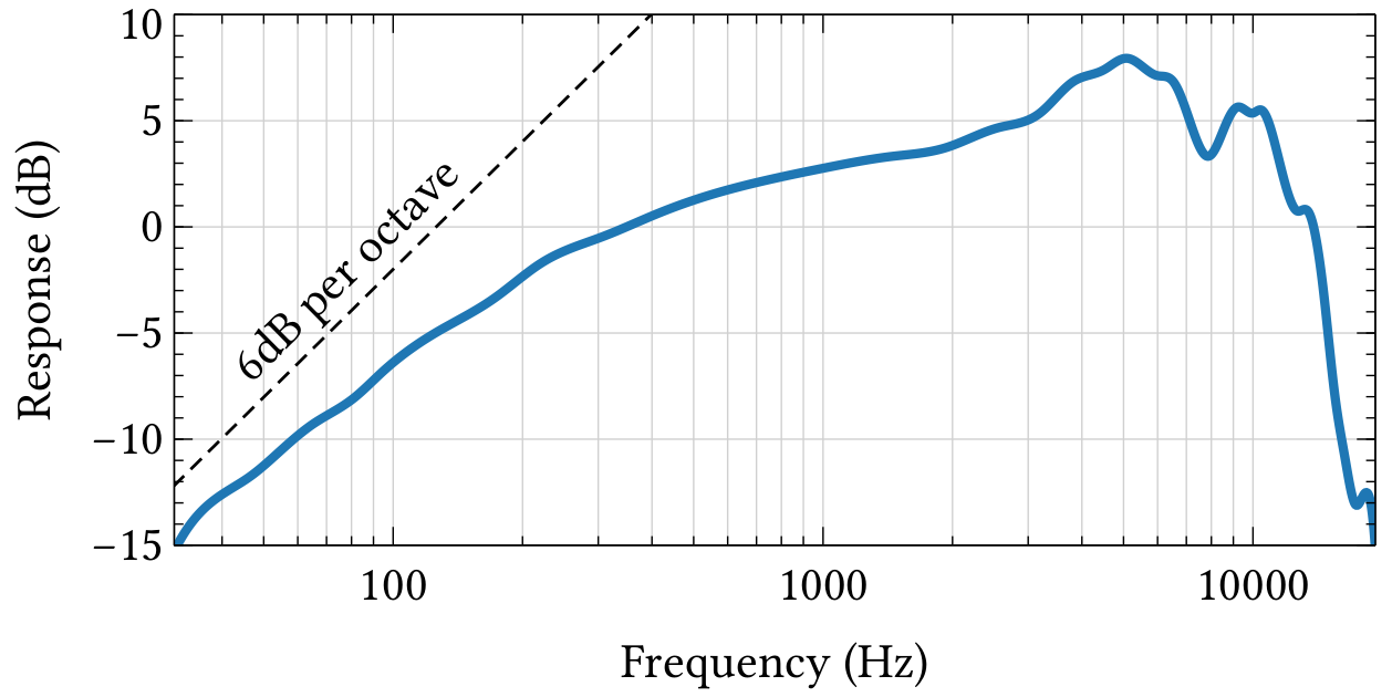
| PDF | PNG | 7.27 | Frequency response of a microphone
|
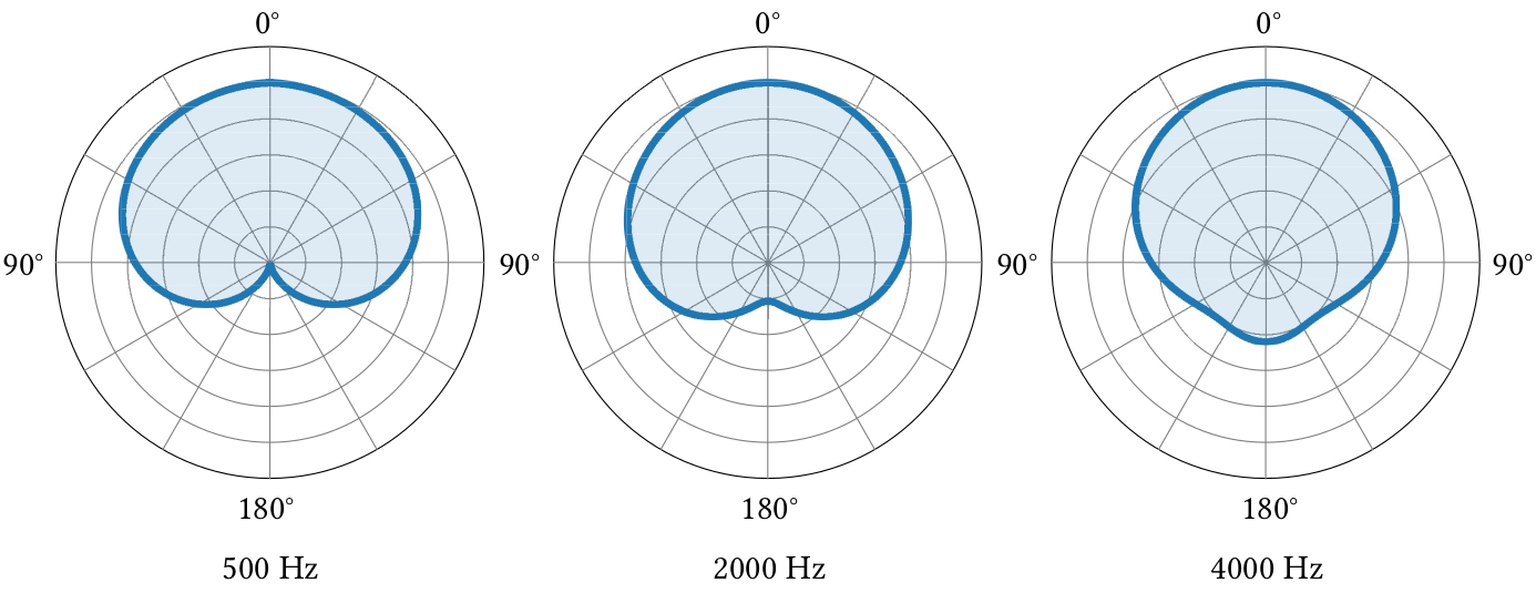
| PDF | PNG | 7.28 | Directionality of a cardioid microphone
|
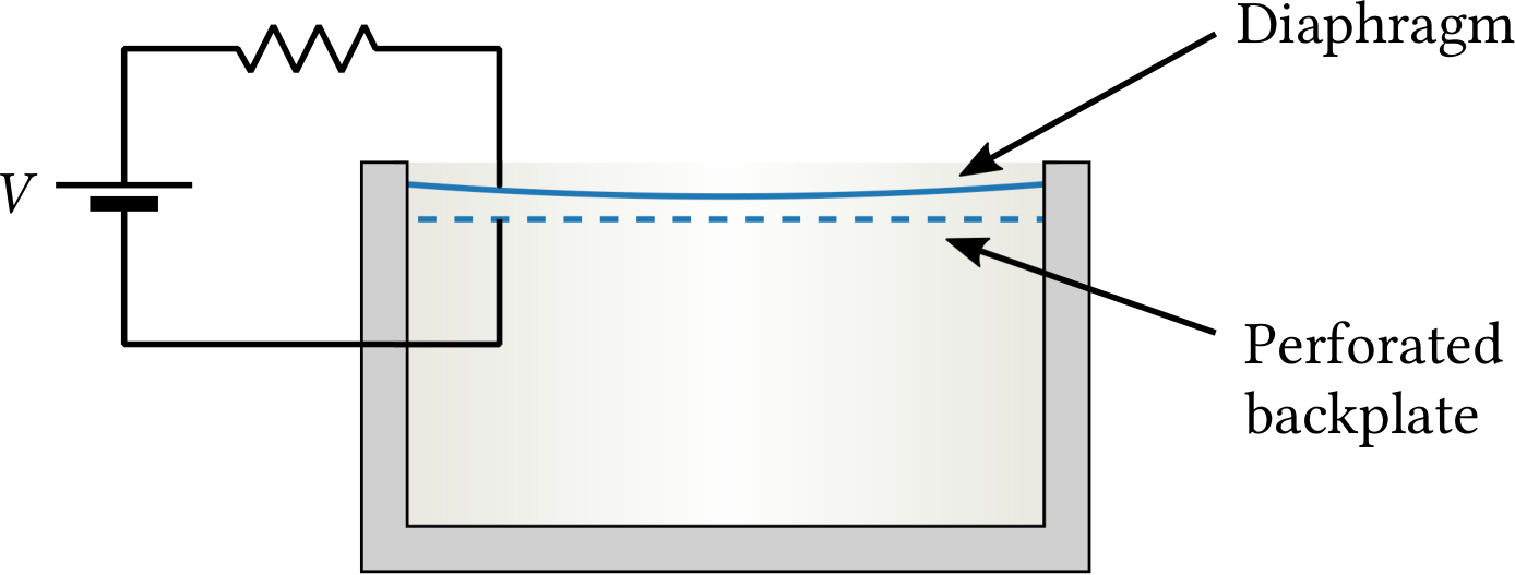
| PDF | PNG | 7.29 | Condenser microphone diagram
|
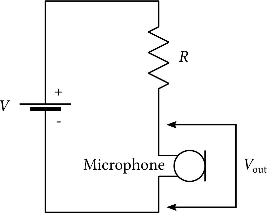
| PDF | PNG | 7.30a | Circuit diagram for a condenser microphone
|
| PDF | PNG | 7.30b | Circuit diagram for a condenser microphone
|
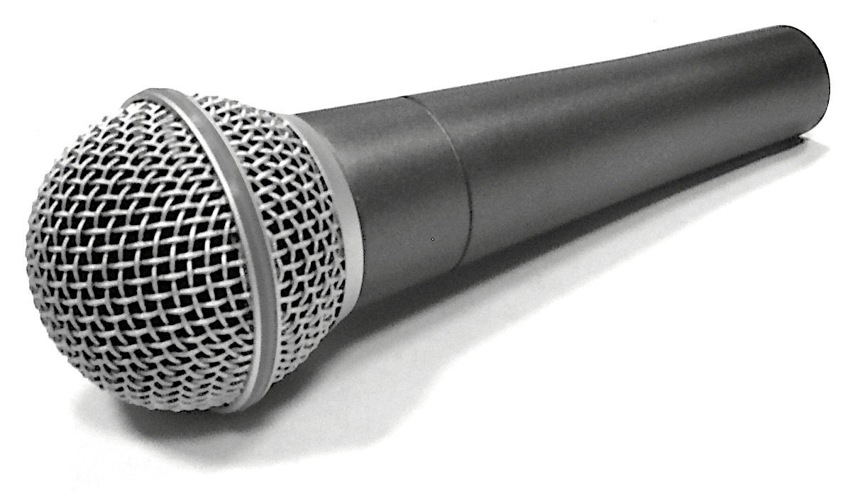
| JPEG | | – | Dynamic microphone photo
|
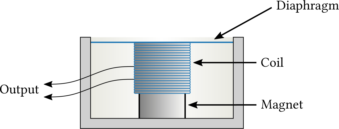
| PDF | PNG | 7.31 | Dynamic microphone diagram
|
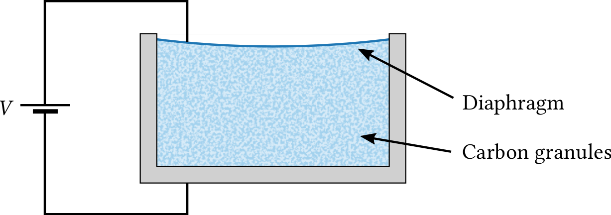
| PDF | PNG | 7.32 | Carbon microphone
|
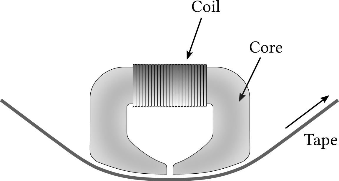
| PDF | PNG | 7.33 | A tape recorder head
|
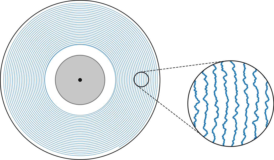
| PDF | PNG | 7.34 | Vinyl LP diagram
|
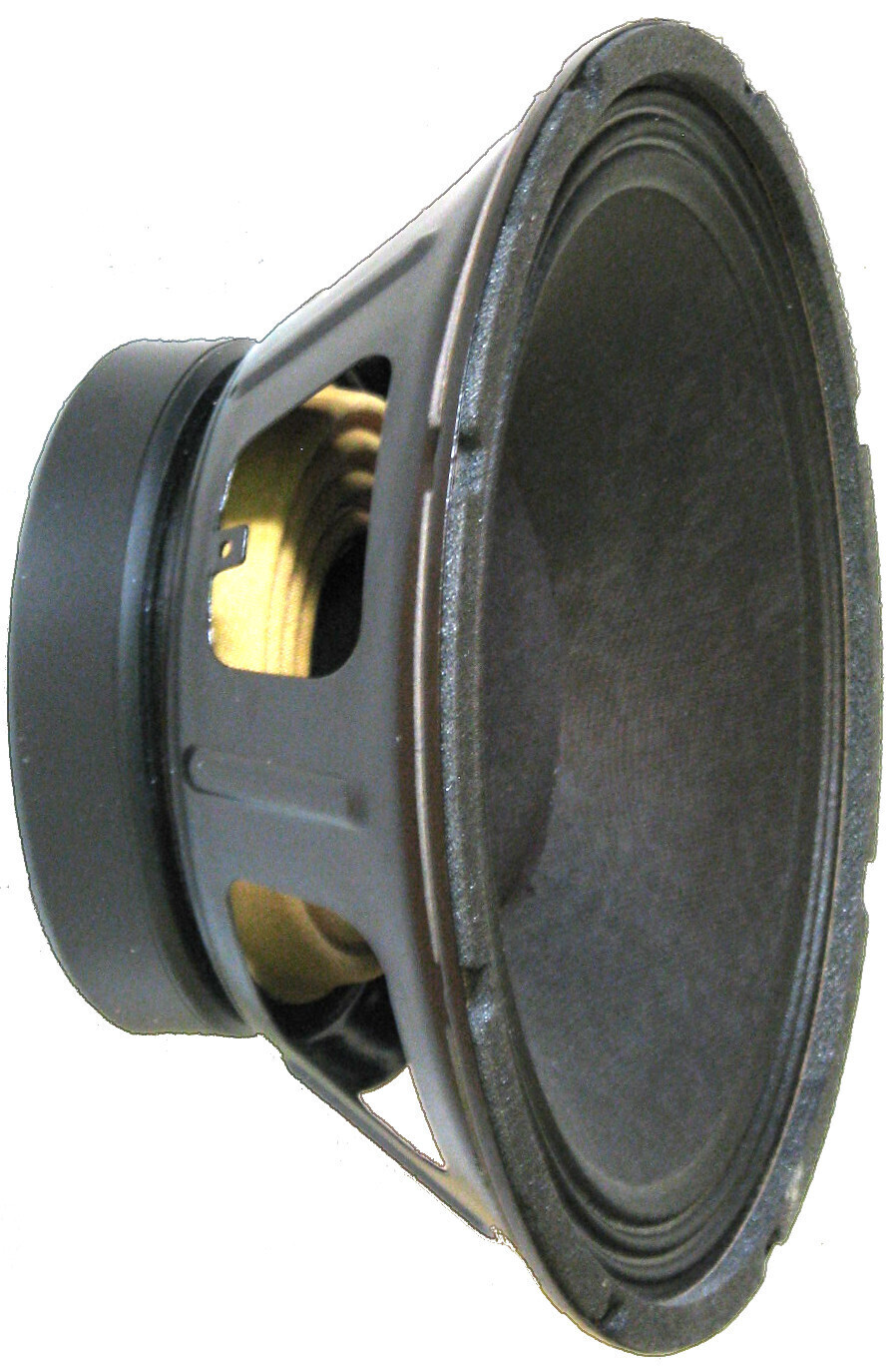
| JPEG | | – | Loudspeaker
|
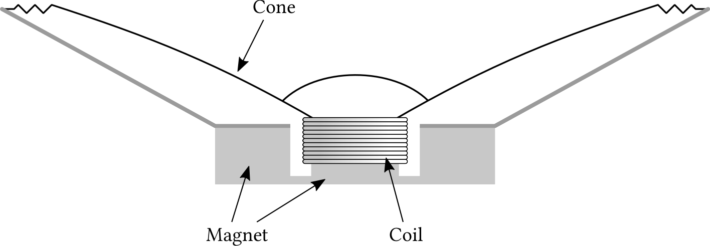
| PDF | PNG | 7.35 | Dynamic loudspeaker
|
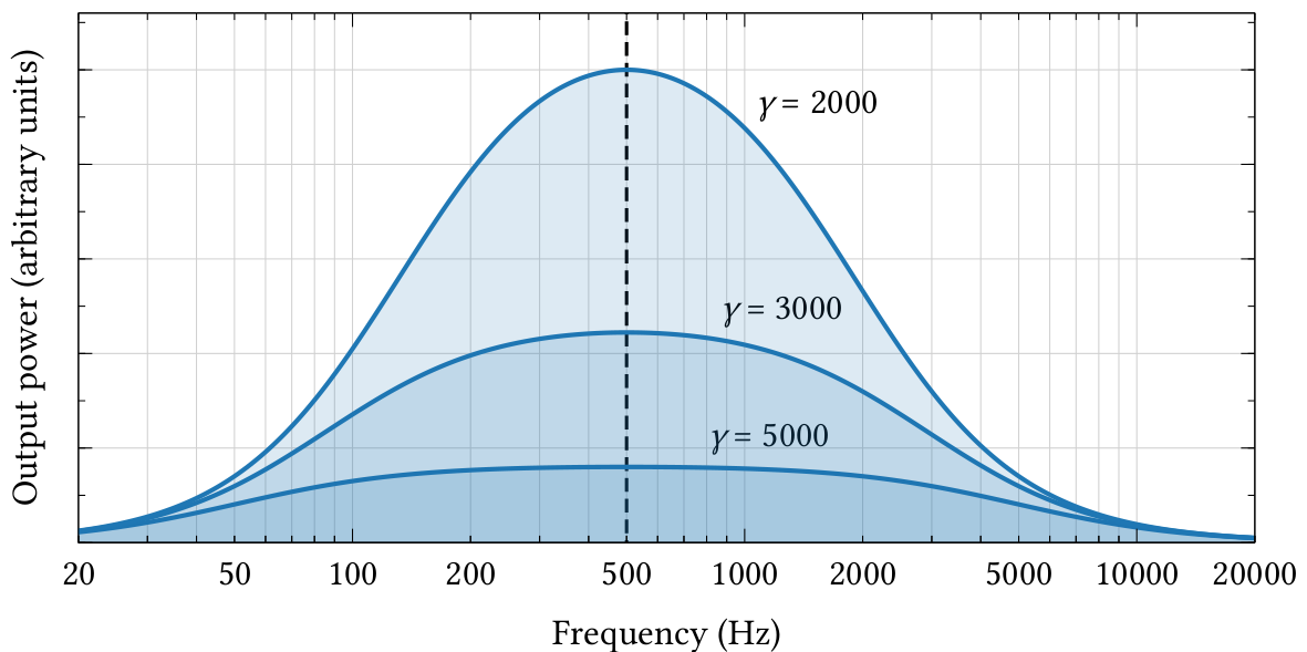
| PDF | PNG | 7.36 | Output power of a loudspeaker
|
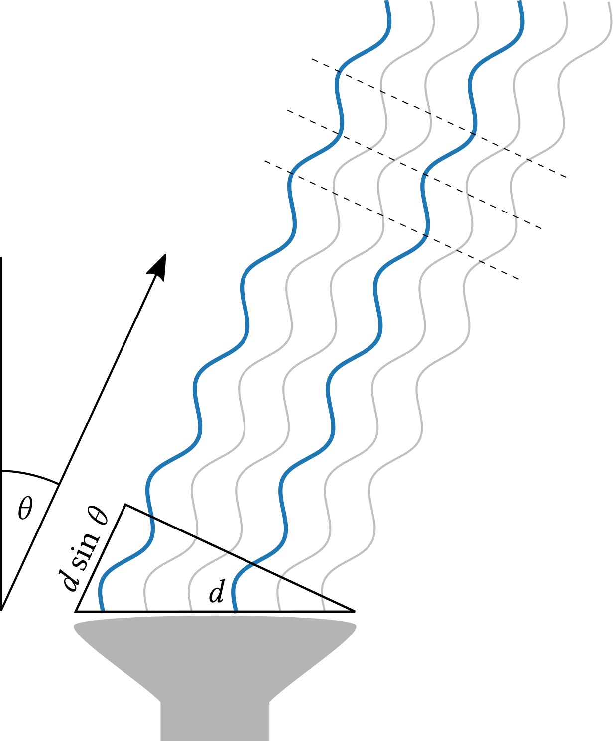
| PDF | PNG | 7.37 | Sound leaving a speaker at an angle
|
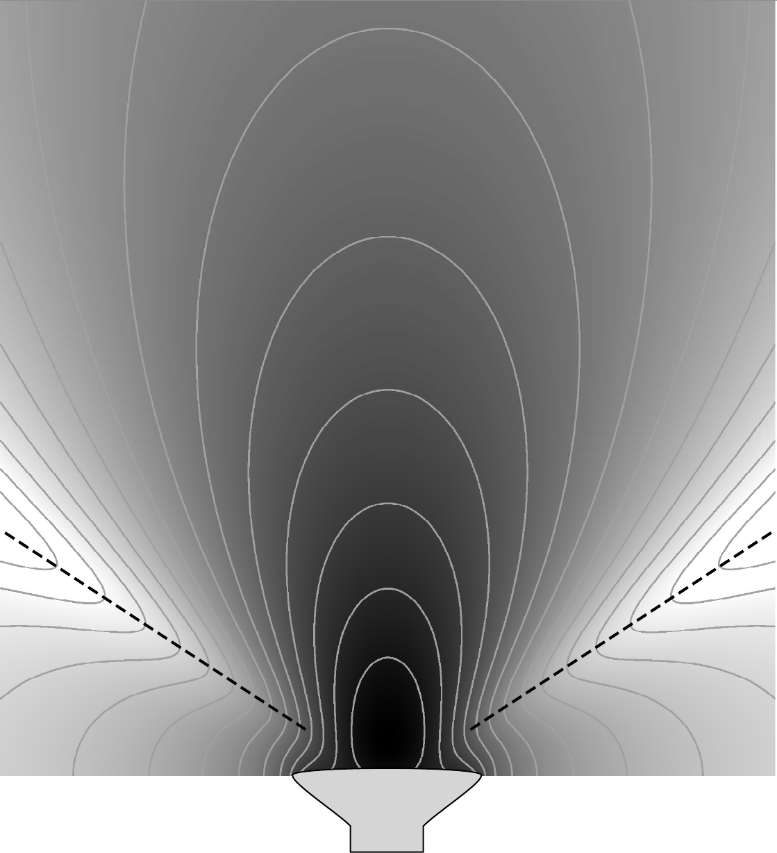
| PDF | PNG | 7.38 | Sound projected by a speaker
|
| PDF | PNG | – | Circular speaker
|
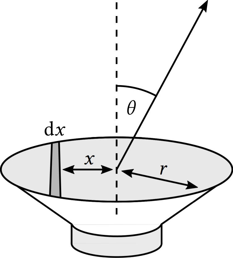
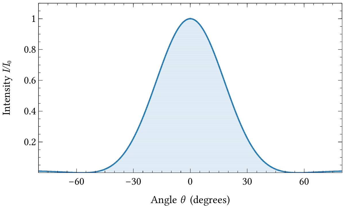
| PDF | PNG | 7.39 | Angular output of a circular loudspeaker
|
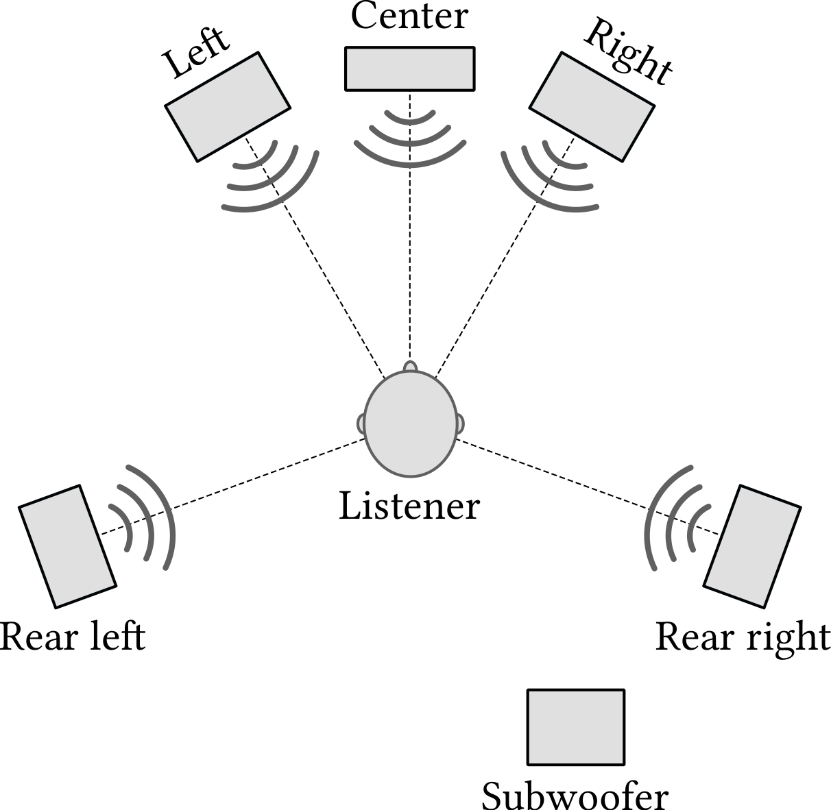
| PDF | PNG | 7.40 | Speaker arrangement for surround sound
|
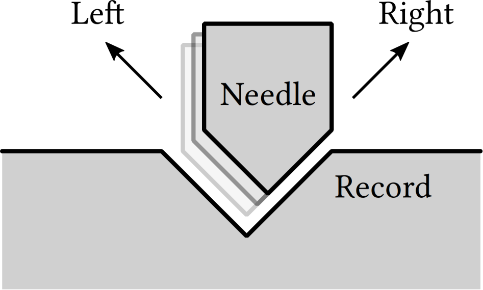
| PDF | PNG | 7.41 | The groove in a stereo LP
|
Chapter 8: Digital audio
| Format | Figure | Description
|
|---|
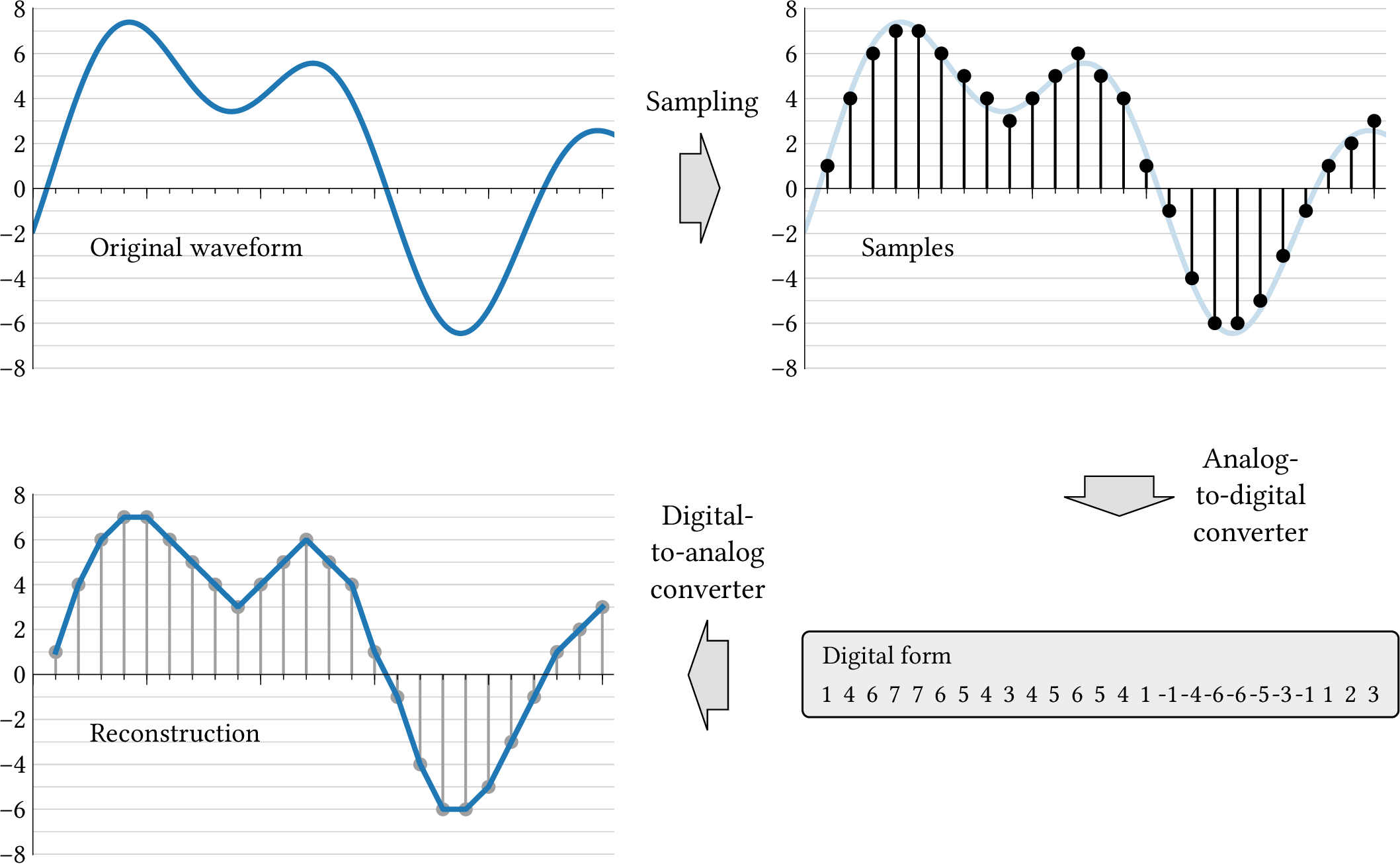
| PDF | PNG | 8.1 | Digitization
|
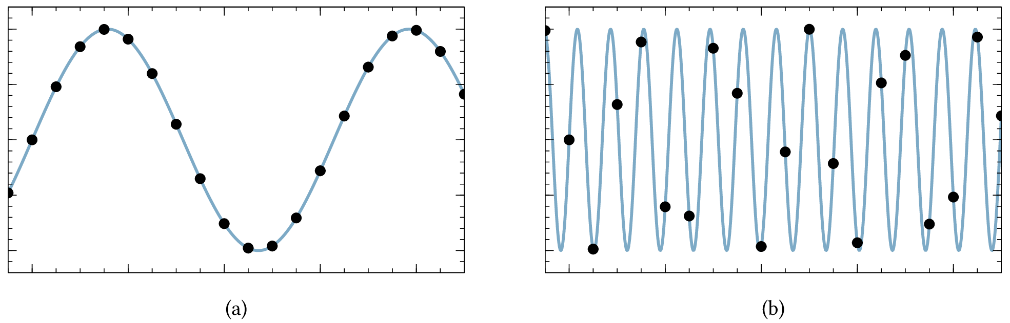
| PDF | PNG | 8.2 | Sampled sine waves
|
| PDF | PNG | 8.3 | Anti-aliasing filter
|
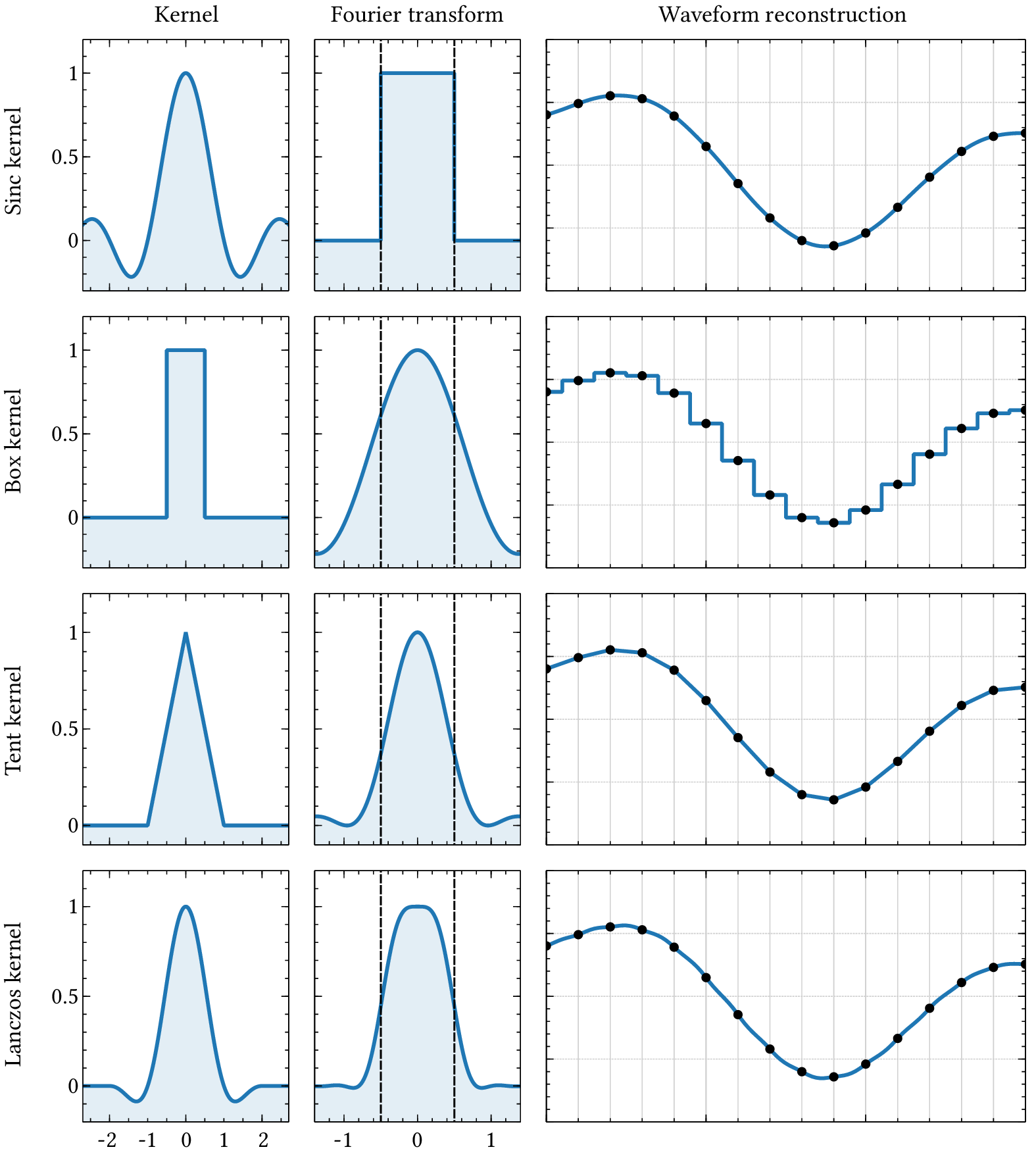
| PDF | PNG | 8.4 | Waveform reconstruction
|
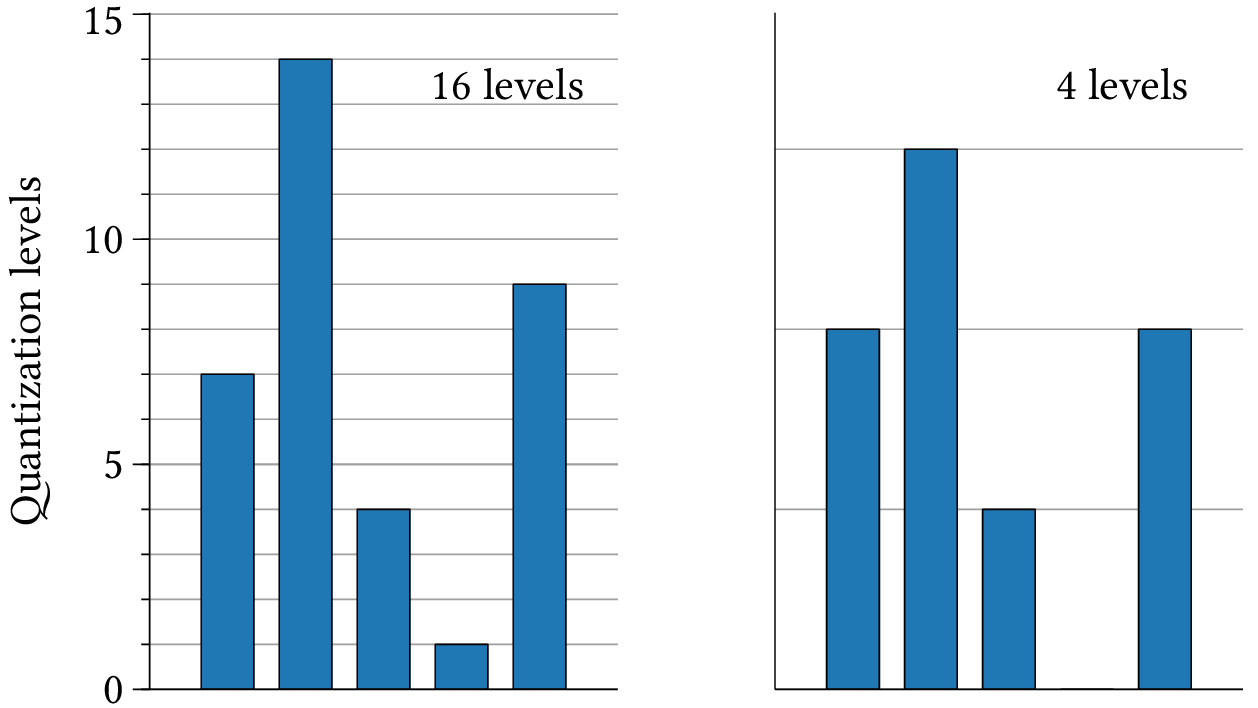
| PDF | PNG | 8.5 | Amplitudes
|
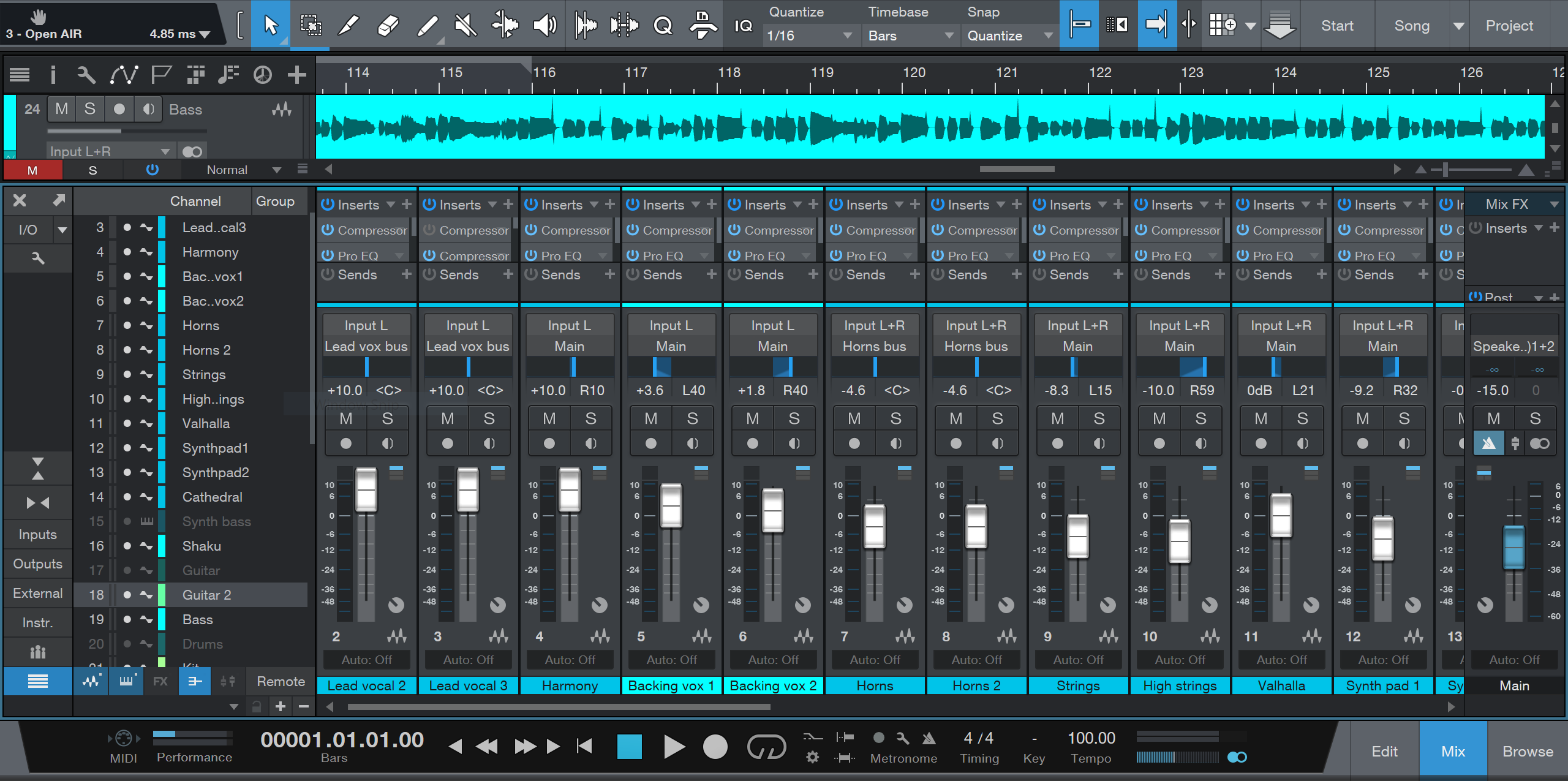
| PNG | 8.6 | Digital recording
|
| JPEG | | 8.7 | Analog-to-digital converter
|
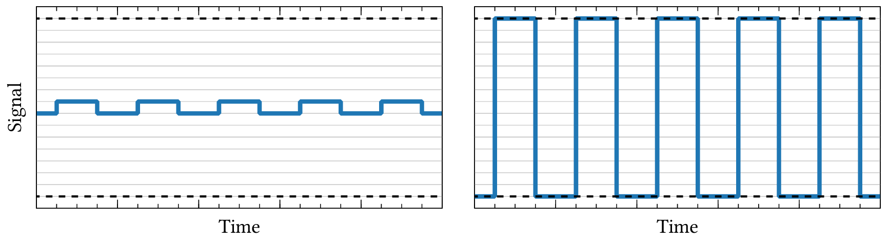
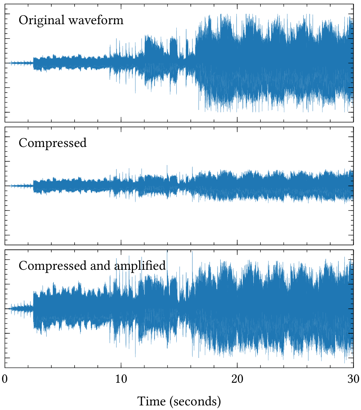
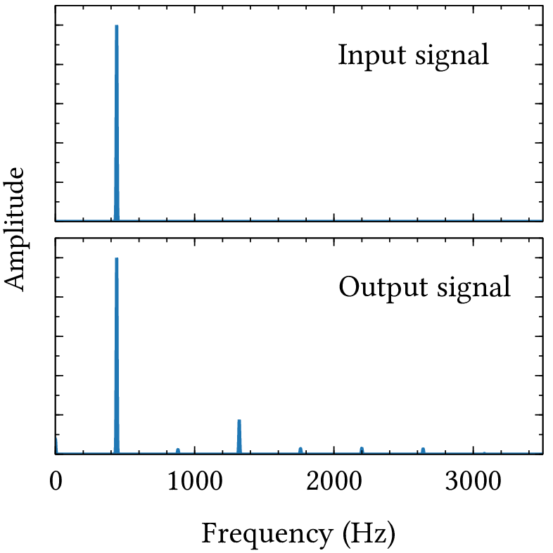
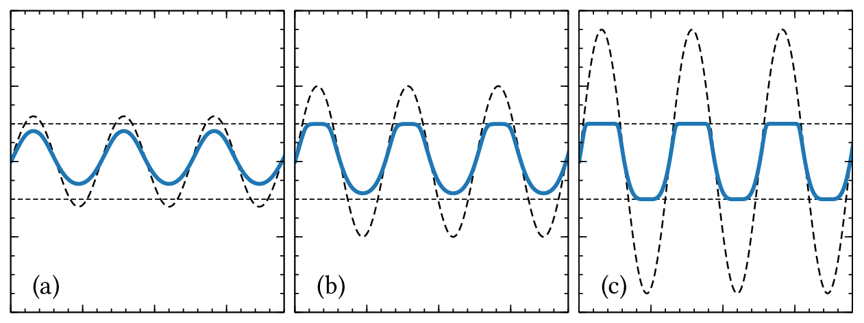
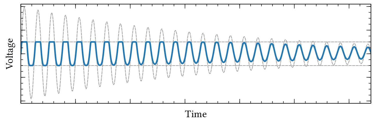
| PDF | PNG | 8.8 | Dynamic compression
|
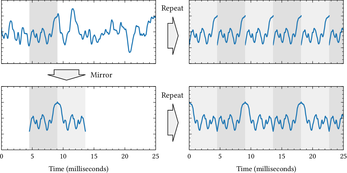
| PDF | PNG | 8.10 | Periodic waveform
|
| PDF | PNG | 8.11 | Decoding
|
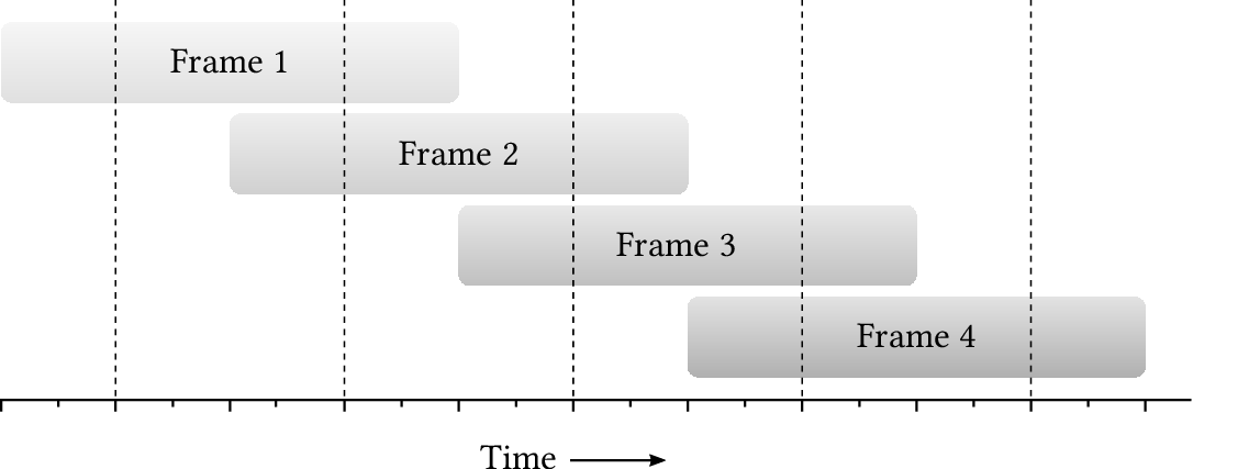
| PDF | PNG | 8.12 | Overlapping frames
|
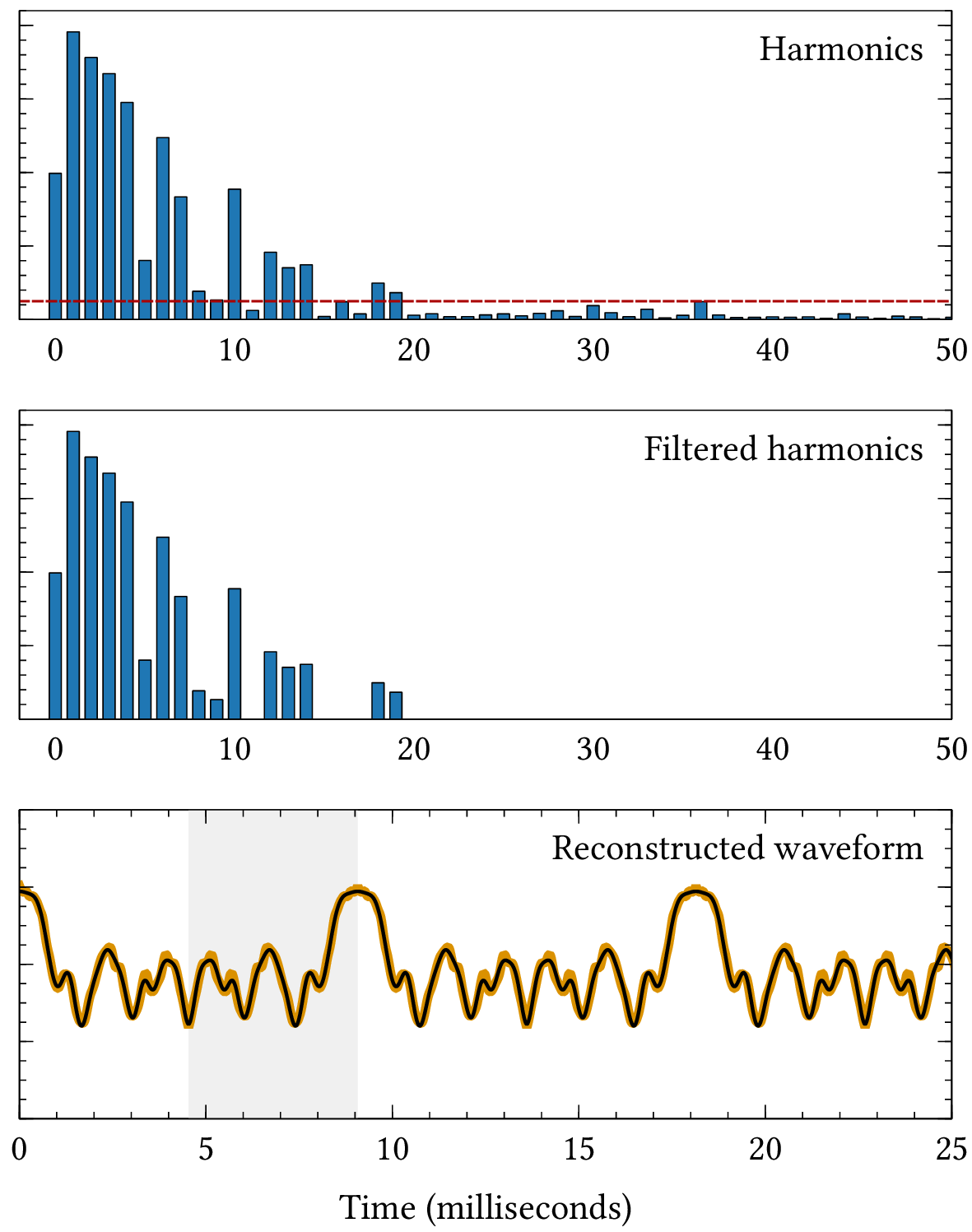
| PDF | PNG | 8.13 | Representing harmonics
|
Chapter 9: Acoustic musical instruments
| Format | Figure | Description |
|---|
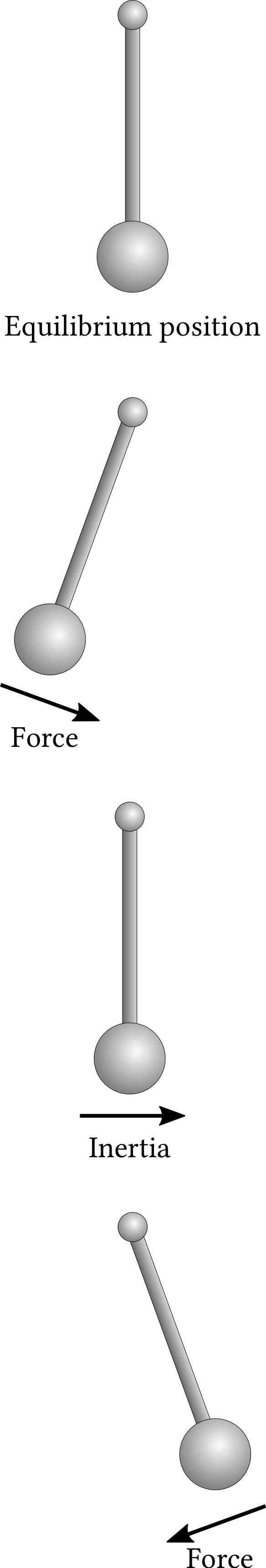
| PDF | PNG | – | Pendulum oscillation
|
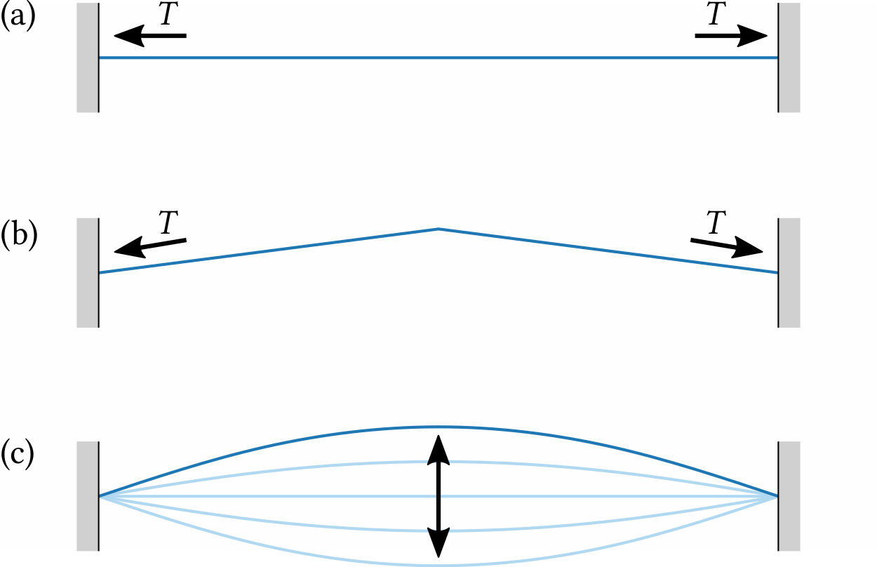
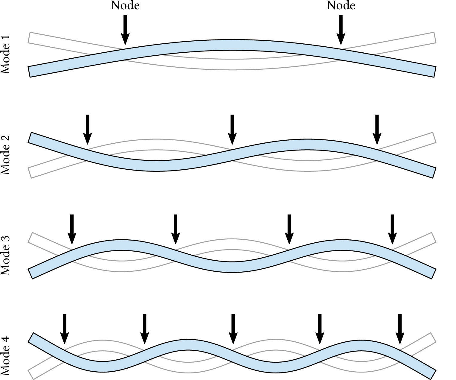
| PDF | PNG | 9.1 | Vibration of a stretched string
|
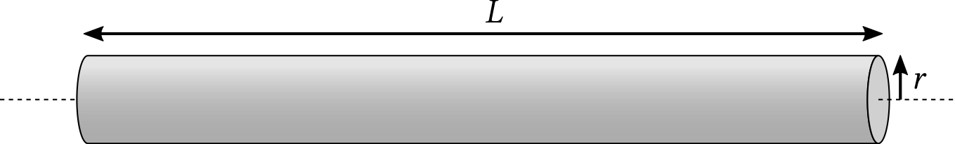
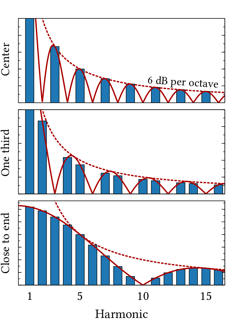
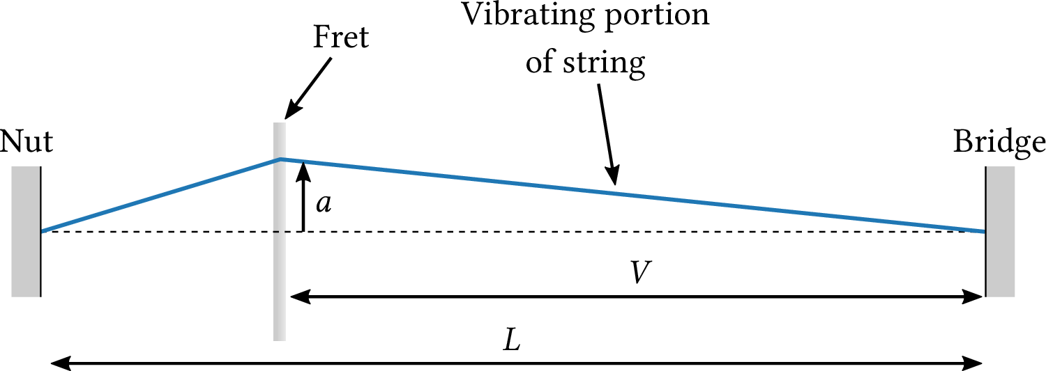
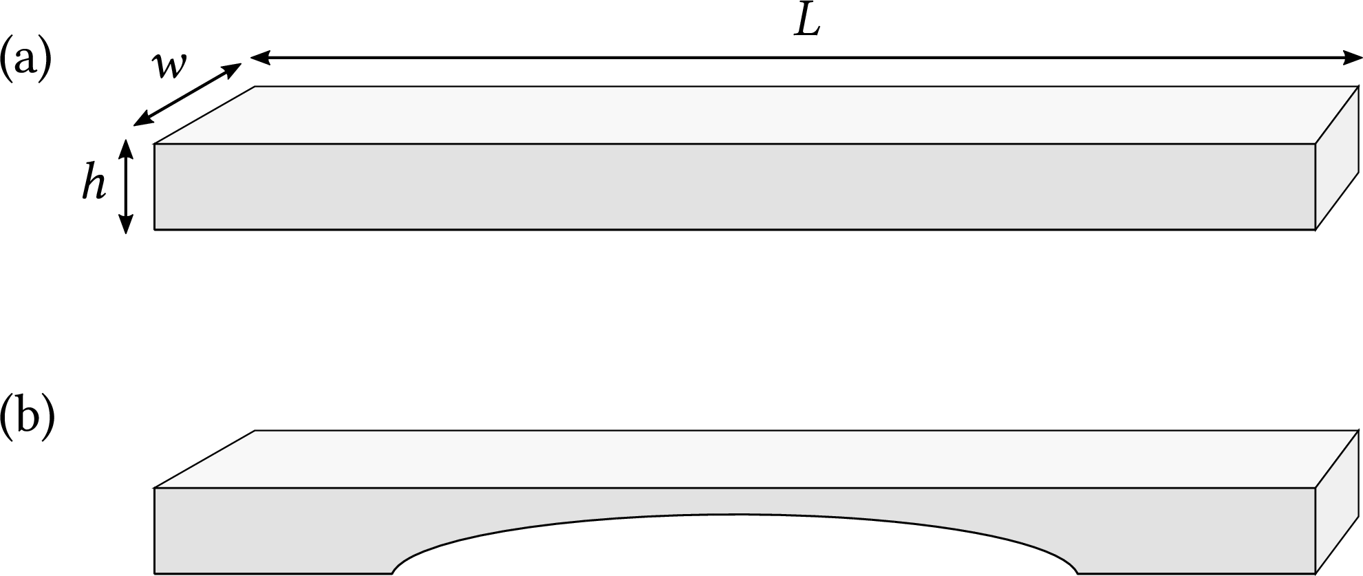
| PDF | PNG | 9.2 | Volume of a string
|
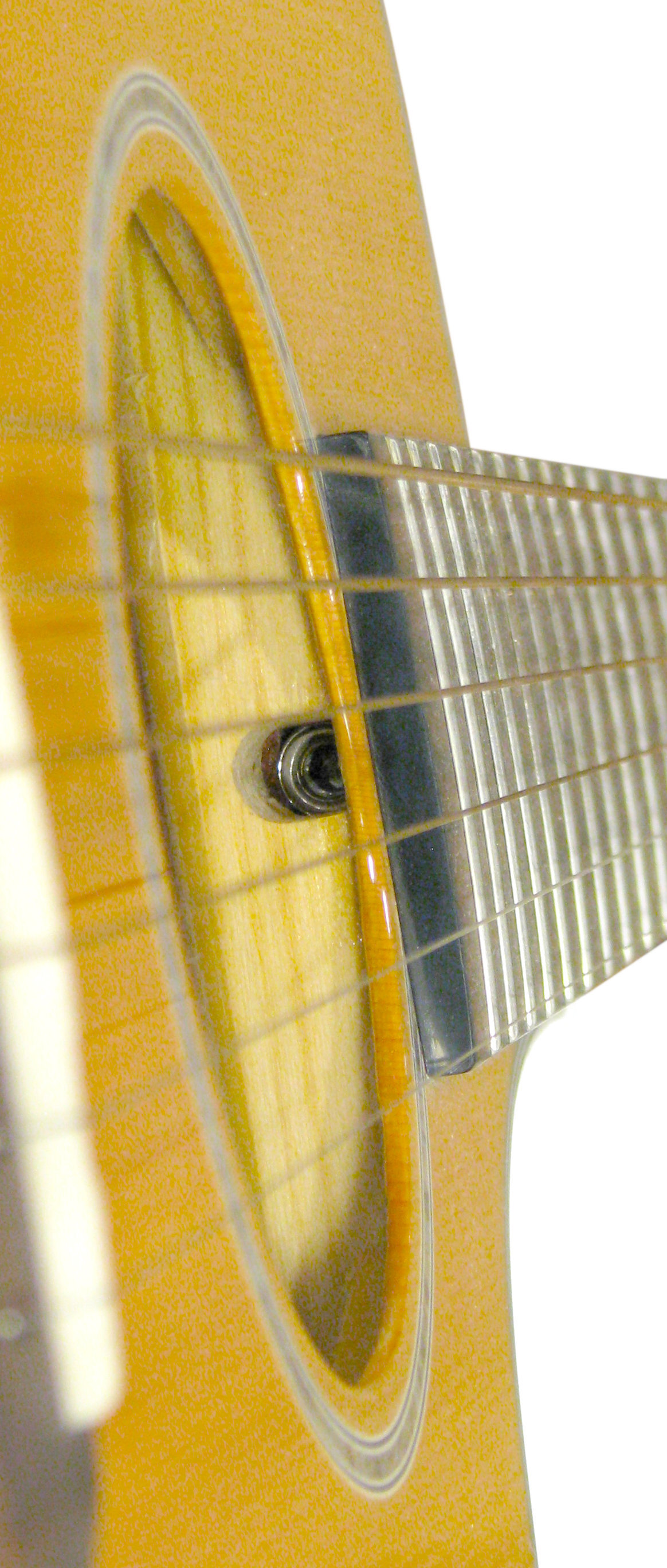
| JPEG | | – | Guitar truss rod
|
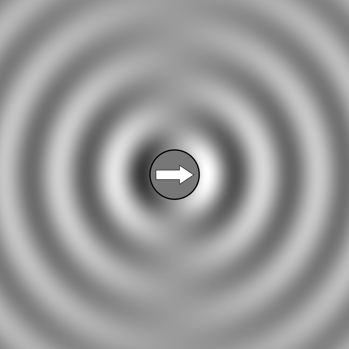
| PDF | PNG | 9.3 | Sound pressure produced by a moving string
|
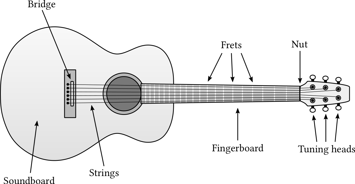
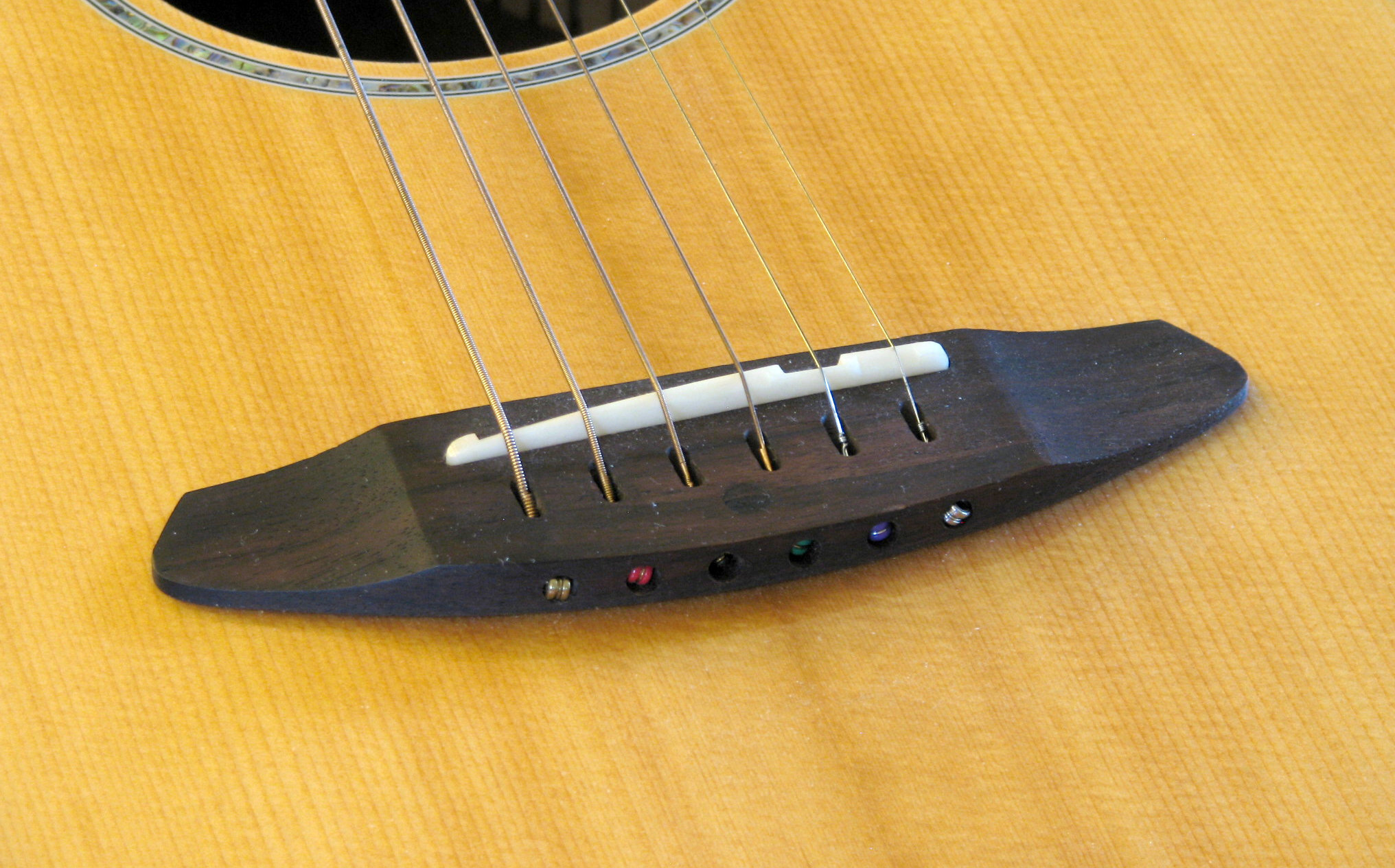
| PDF | PNG | 9.4 | Acoustic guitar
|
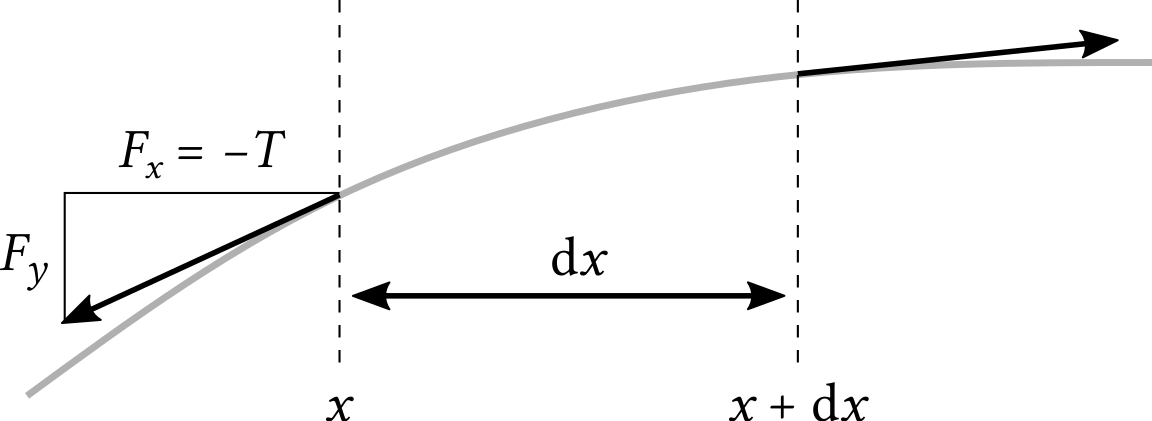
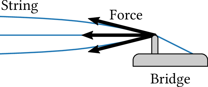
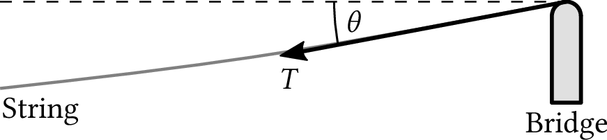
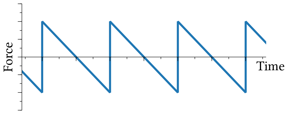
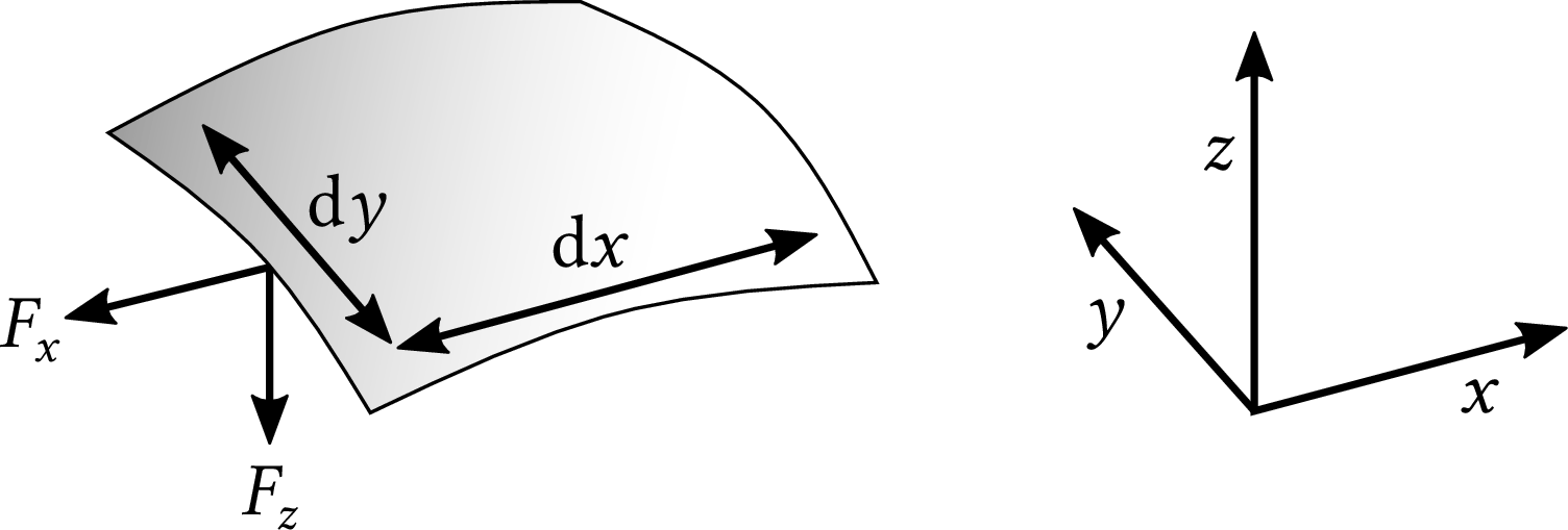
| PDF | PNG | 9.5 | Forces acting on a string
|
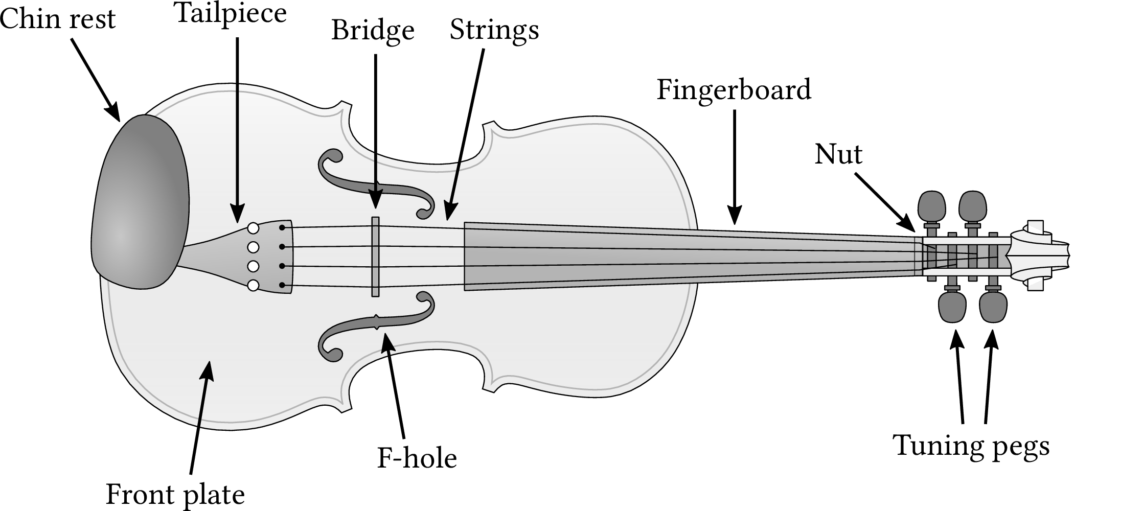
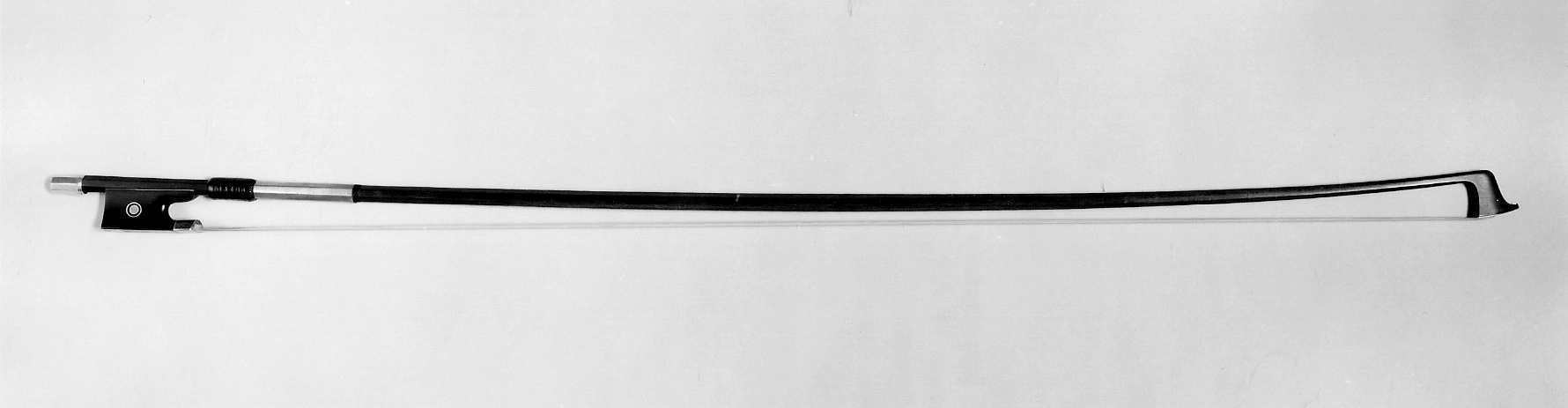
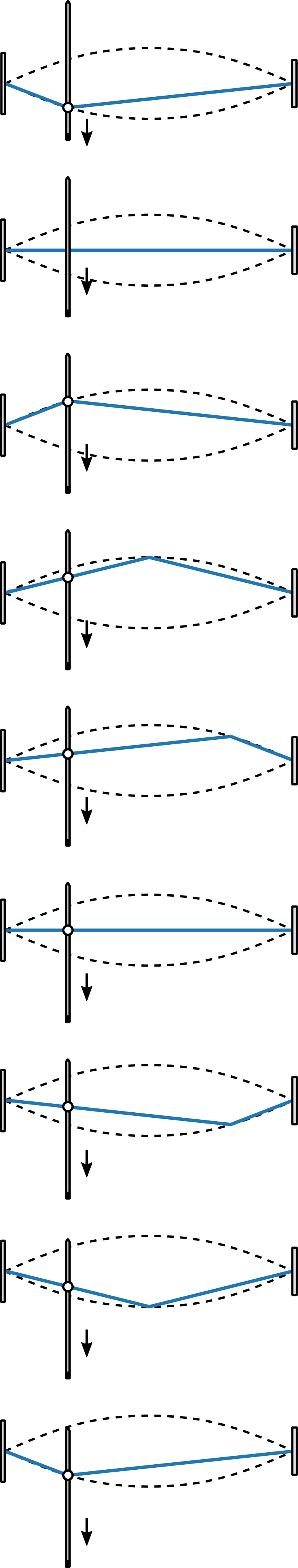
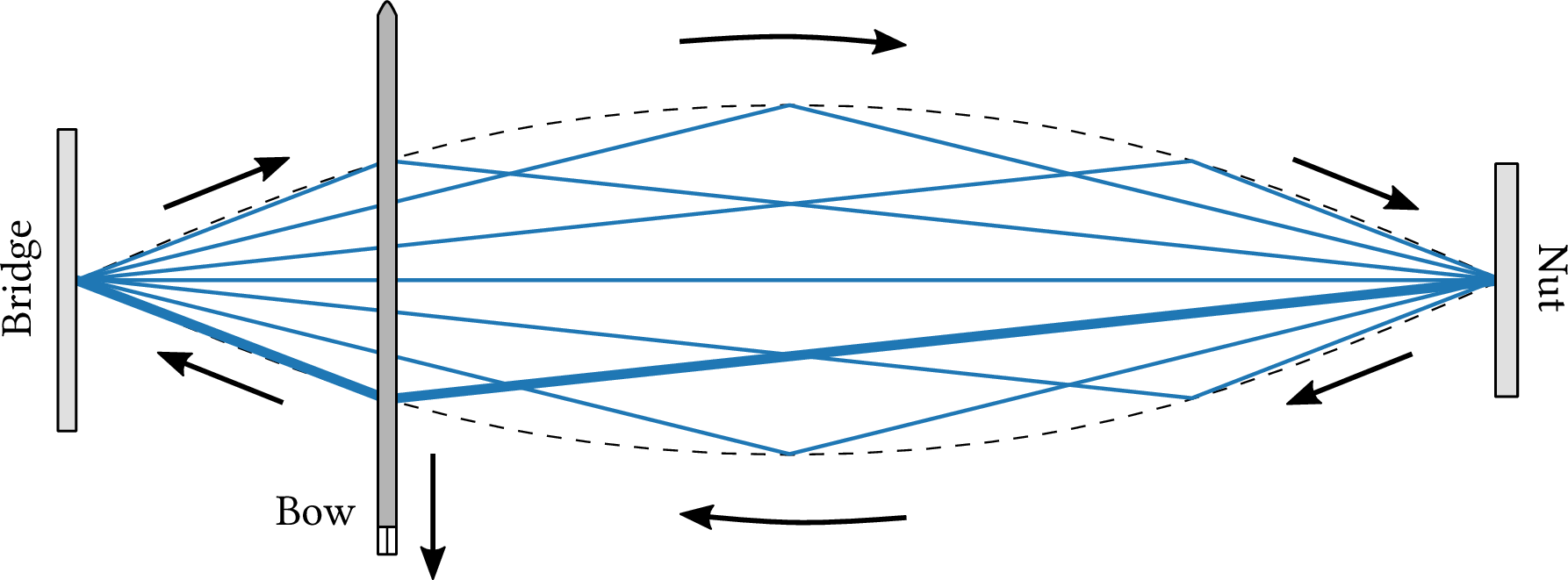
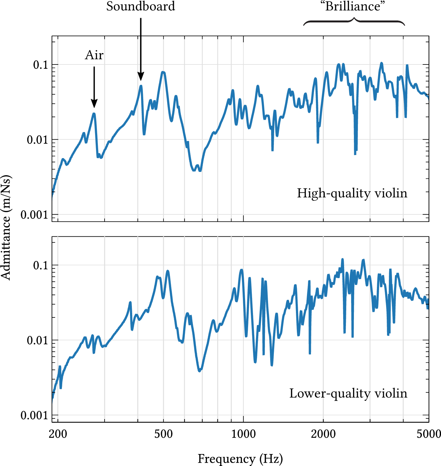
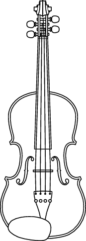
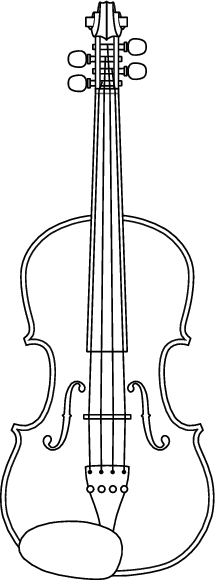
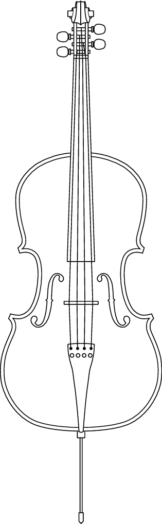
Chapter 10: String instruments
Chapter 11: Wind and brass instruments
| Format | Figure | Description |
|---|
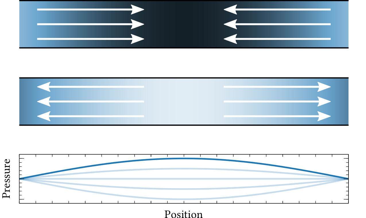
| PDF | PNG | 11.1 | Vibration of air in a pipe
|
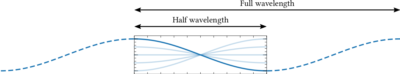
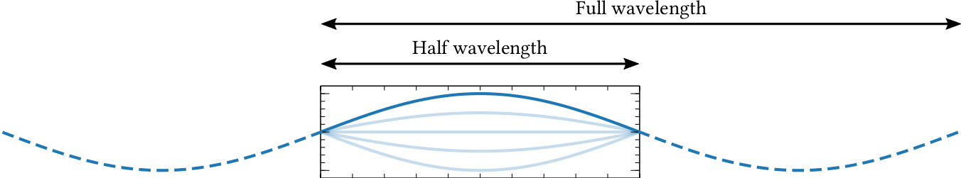
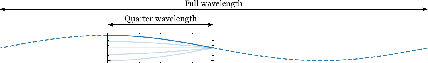
| PDF | PNG | 11.2 | Wavelength of a standing wave
|
| PDF | PNG | 11.3 | Vibration of air in an open-ended pipe
|
| PDF | PNG | 11.4 | Standing wave in an open pipe
|
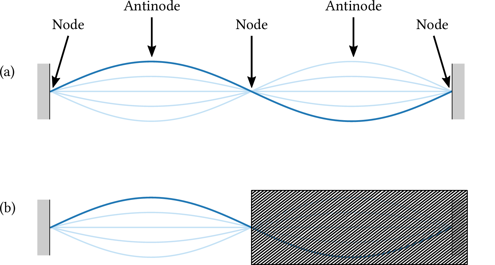
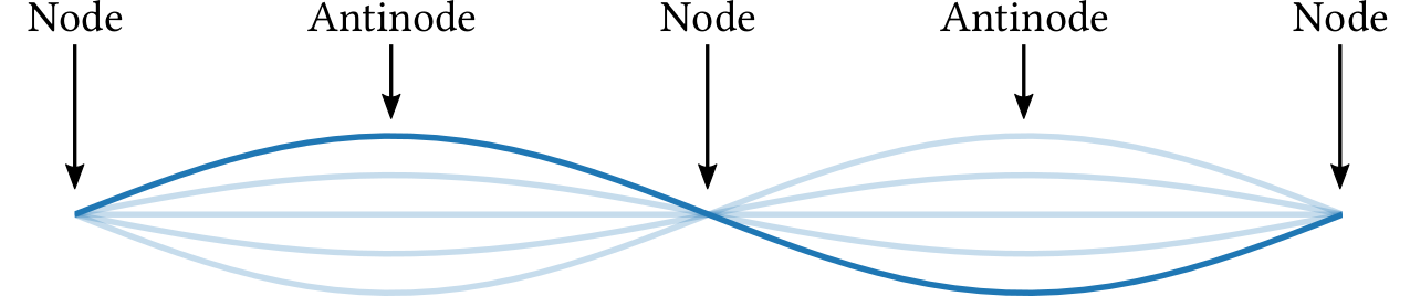
| PDF | PNG | – | Nodes and antinodes
|
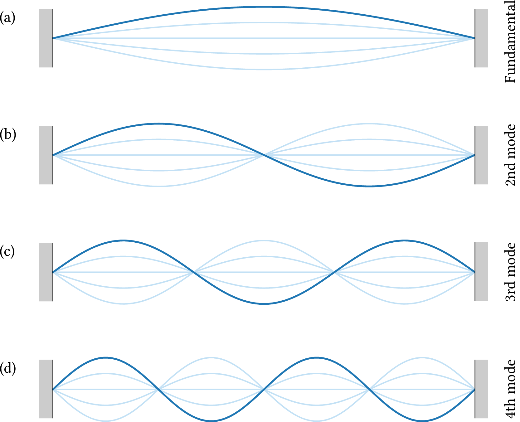
| PDF | PNG | 11.5 | Modes of vibration of a pipe
|
| PDF | PNG | 11.6 | Frequency spectrum of a flute note
|
| PDF | PNG | 11.8 | Vibration in a pipe closed at one end
|
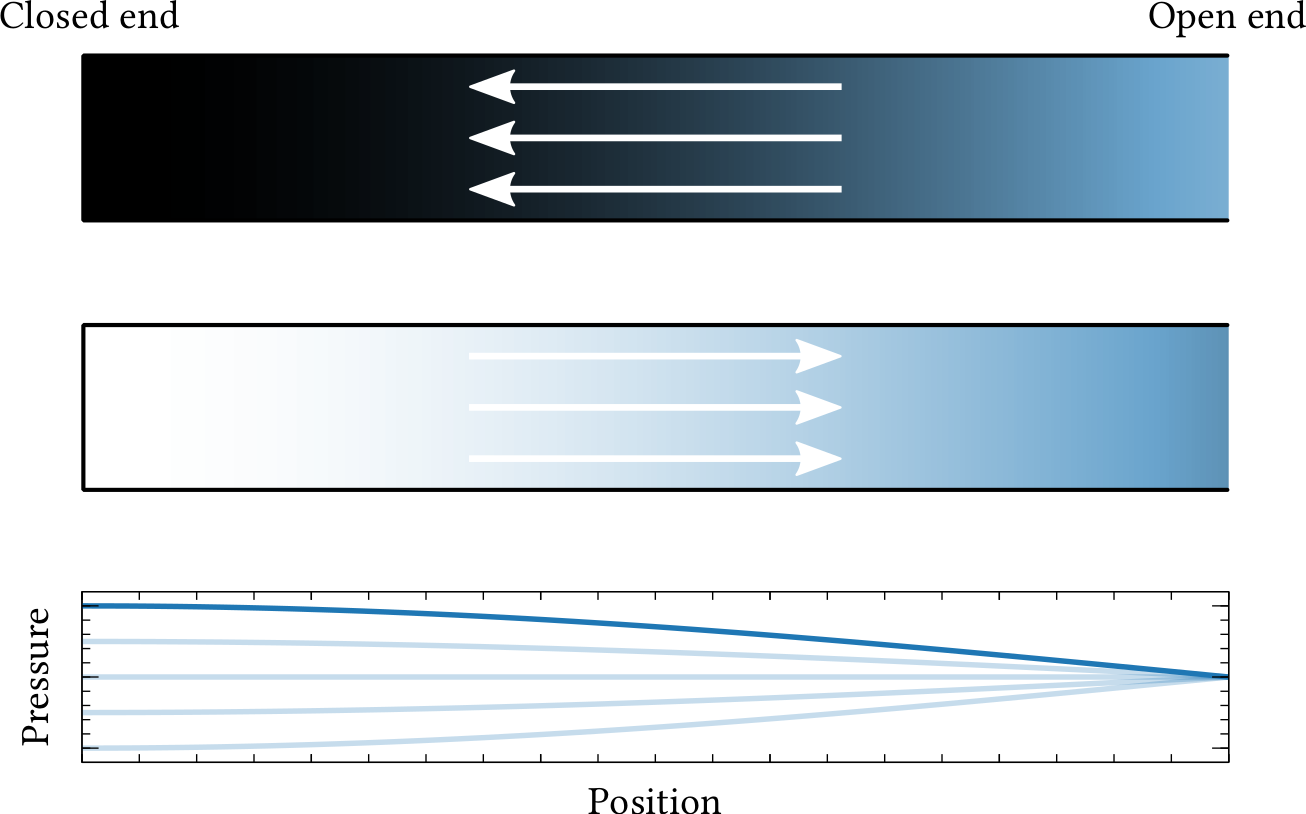
| PDF | PNG | 11.9 | Standing wave in a closed pipe
|
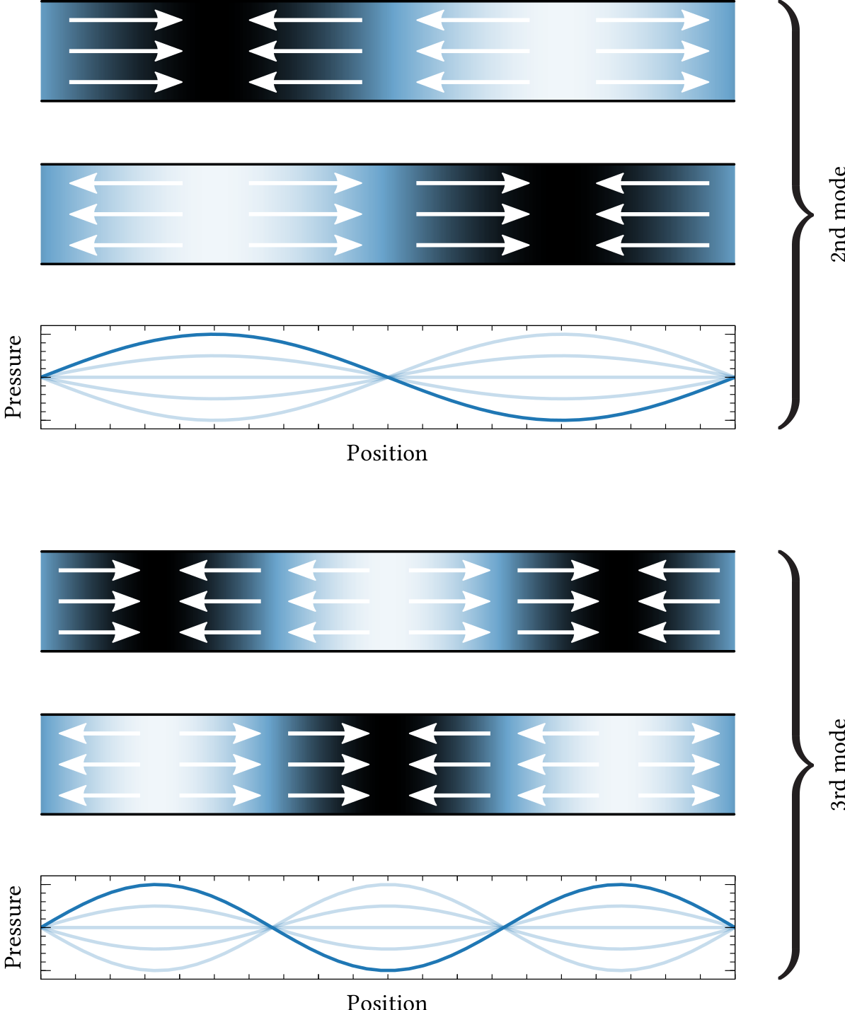
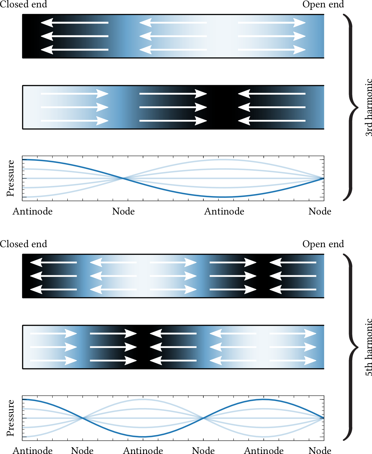
| PDF | PNG | 11.10 | Modes in a closed pipe
|
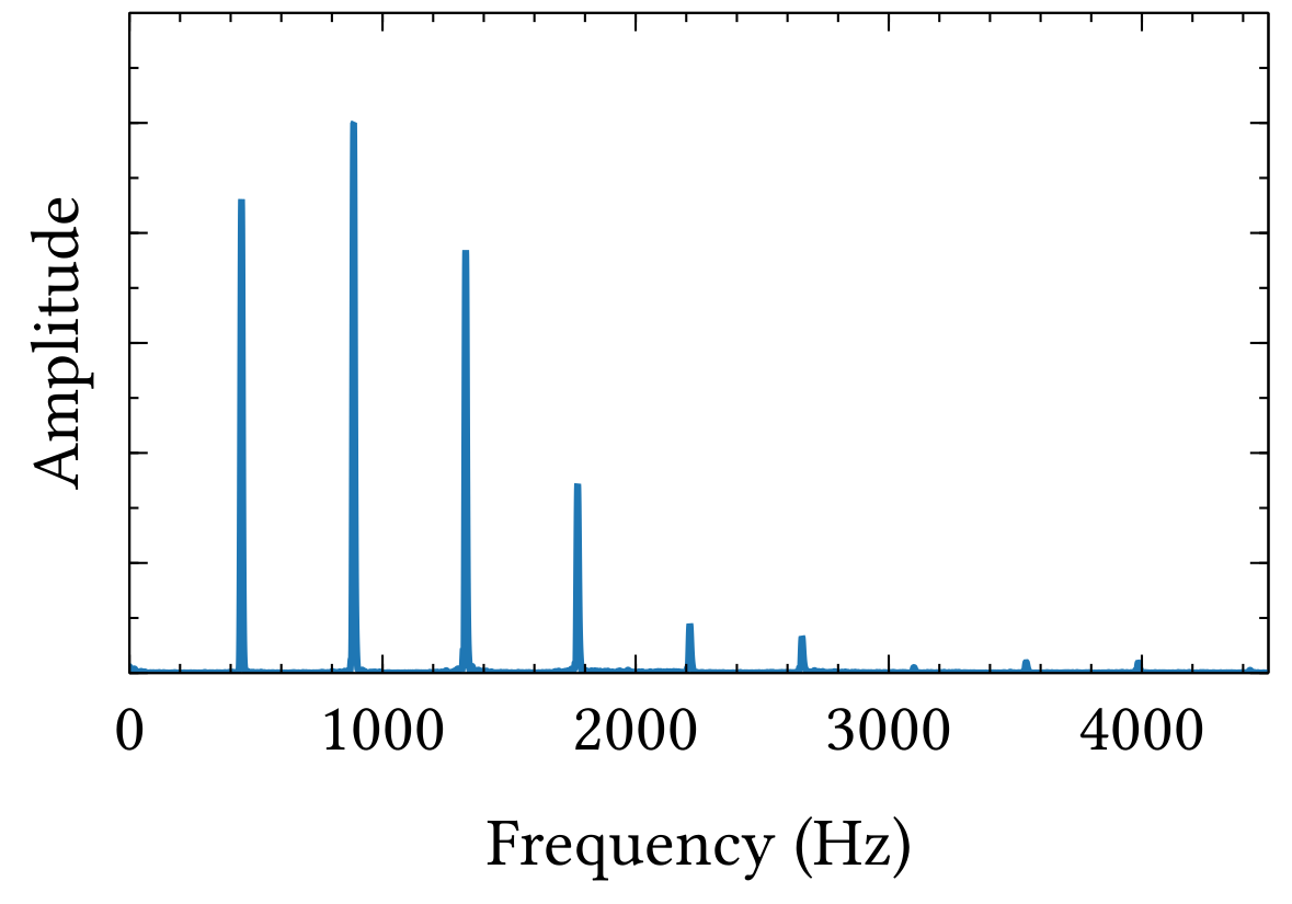
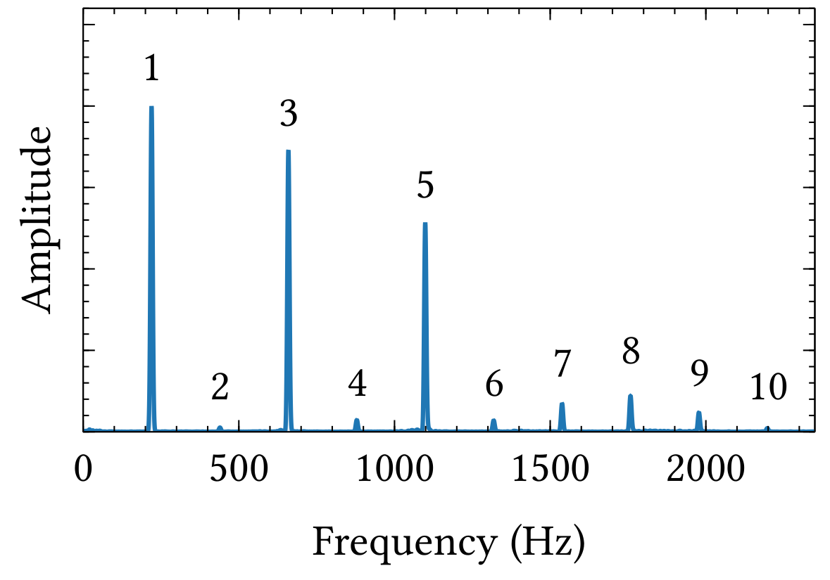
| PDF | PNG | 11.11 | Frequency spectrum of a clarinet
|
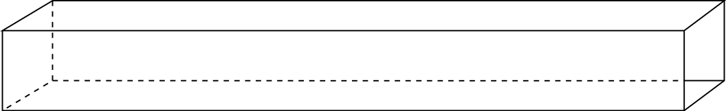
| PDF | PNG | – | Square pipe
|
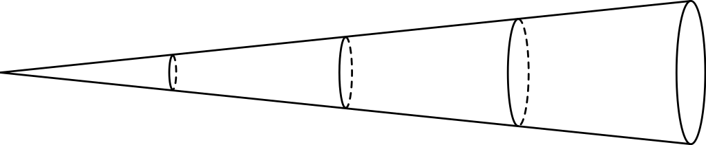
| PDF | PNG | – | Conical pipe
|
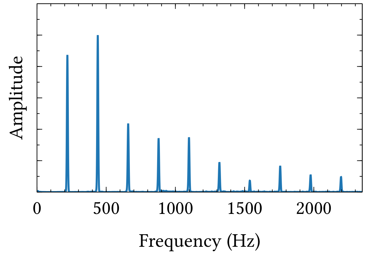
| PDF | PNG | 11.12 | Frequency spectrum of a saxophone
|
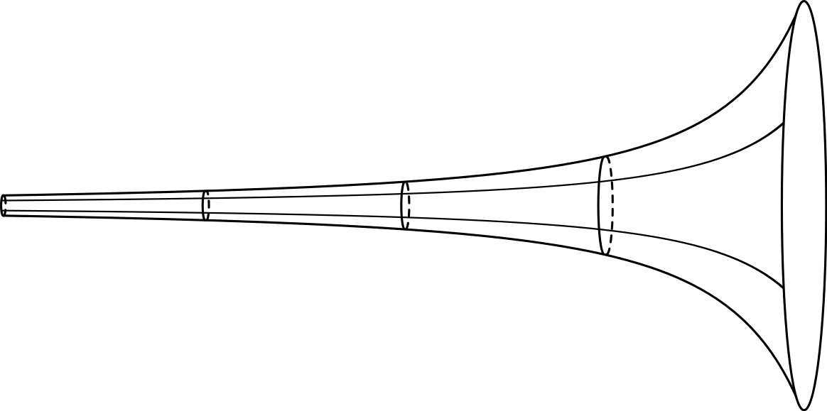
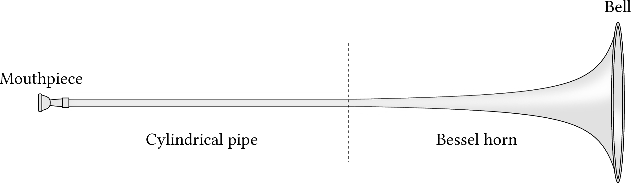
| PDF | PNG | – | Bessel horn
|
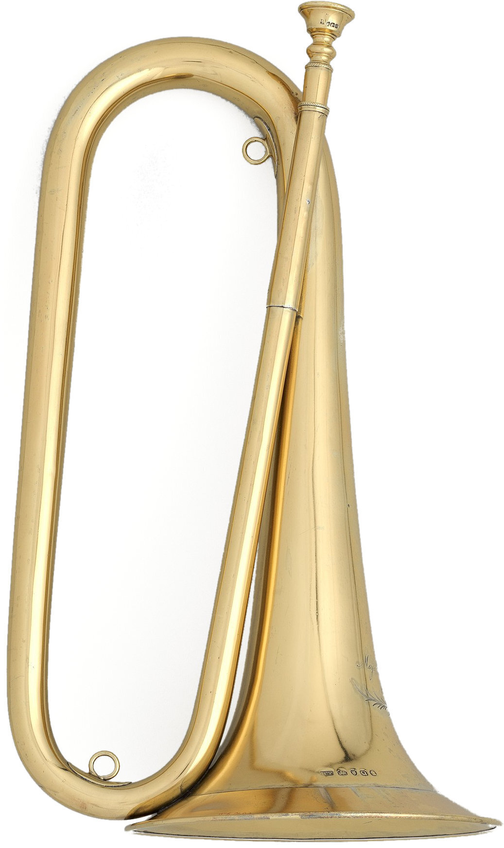
| JPEG | | – | Bugle
|
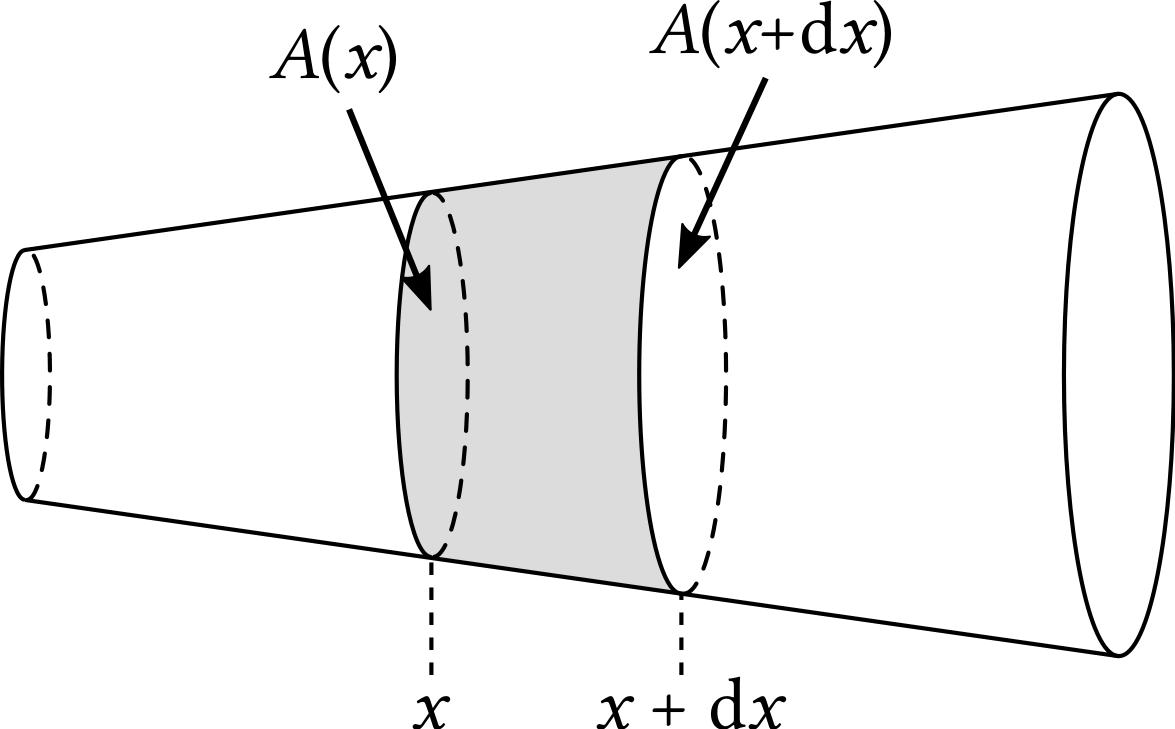
| PDF | PNG | – | Cone segment
|
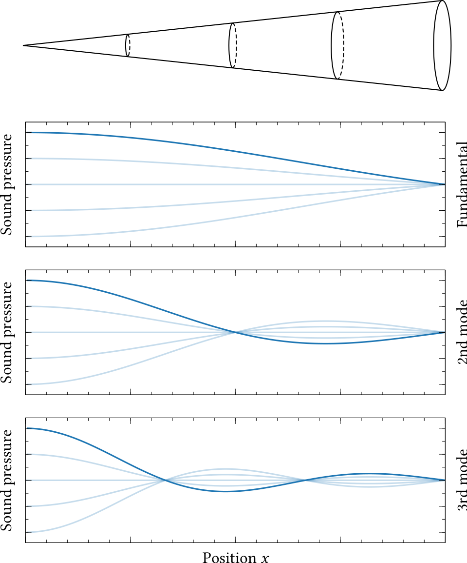
| PDF | PNG | 11.13 | Pressure in a conical pipe
|
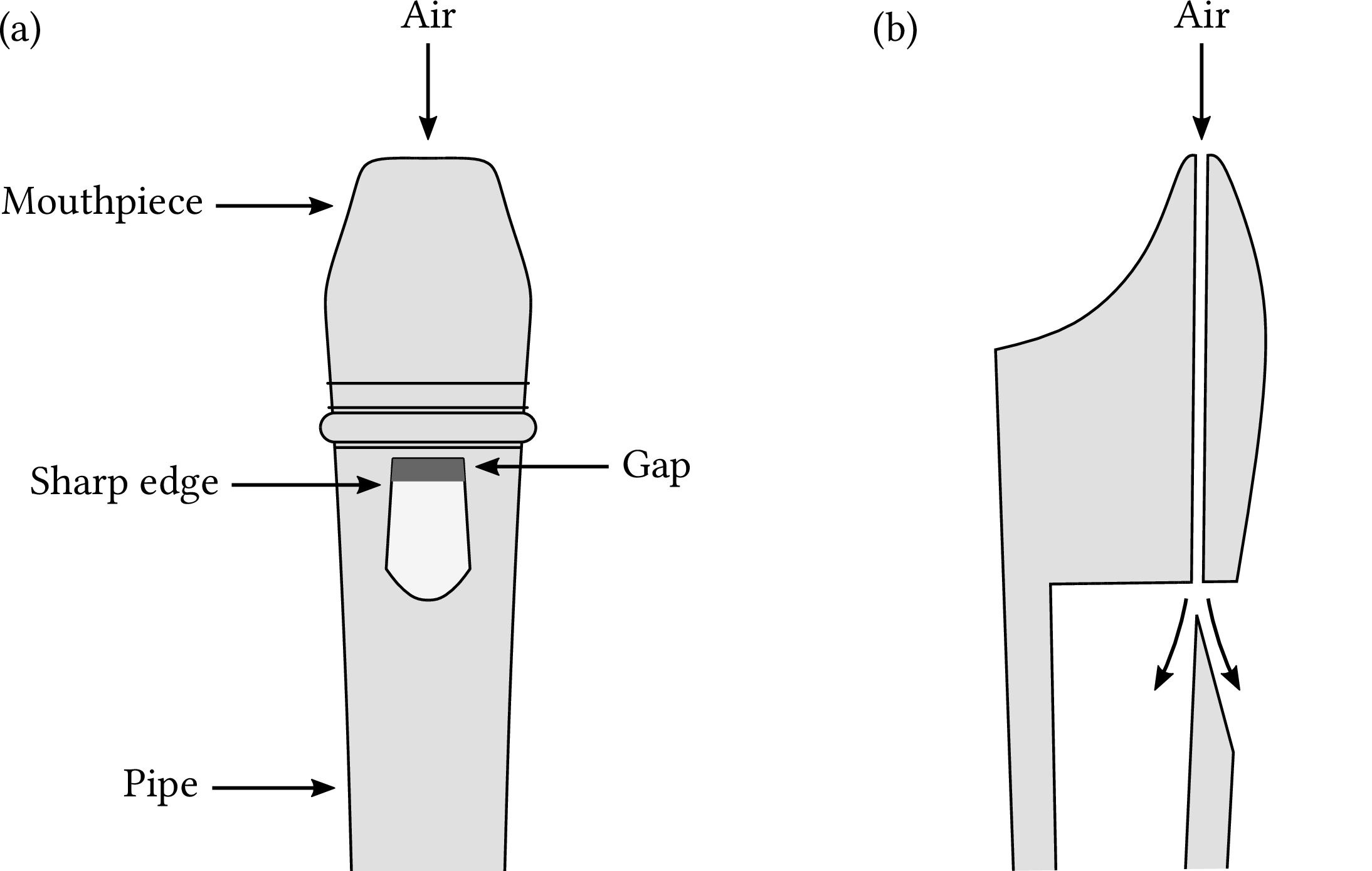
| PDF | PNG | 11.14 | Tone production in a recorder
|
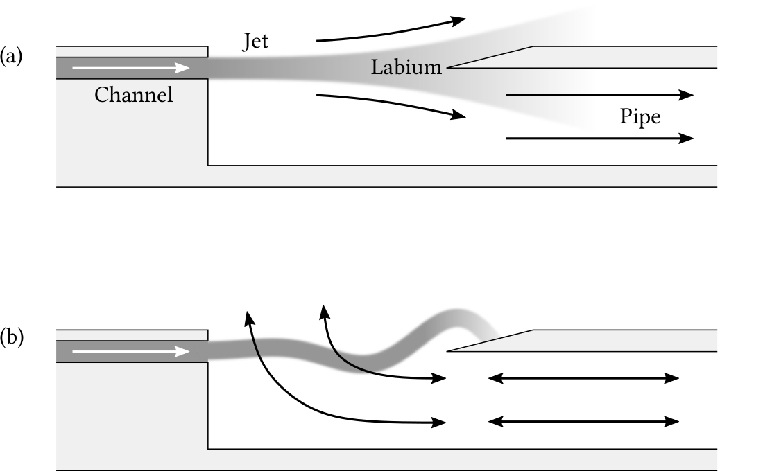
| PDF | PNG | 11.15 | Jet-drive mechanism
|
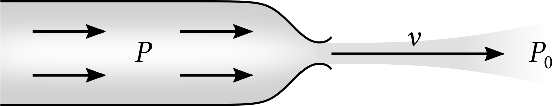
| PDF | PNG | 11.16 | Bernoulli's principle
|
| PDF | PNG | 11.17 | Geometry of air jet
|
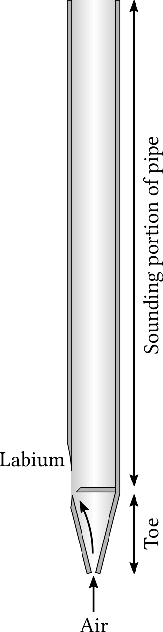
| PDF | PNG | 11.18 | Interior of an organ pipe
|
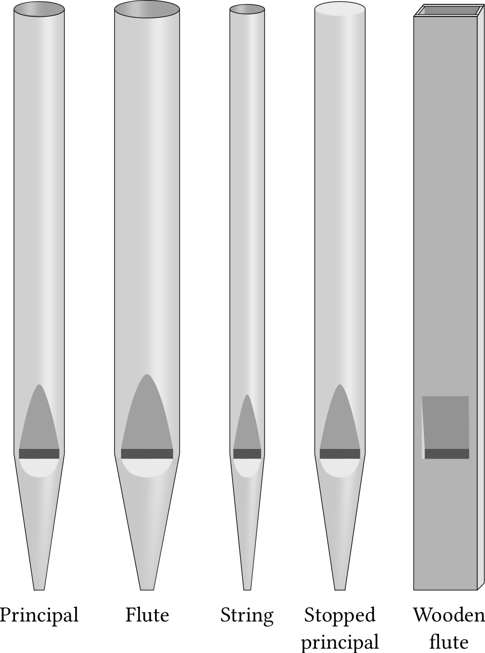
| PDF | PNG | 11.19 | Types of organ pipes
|
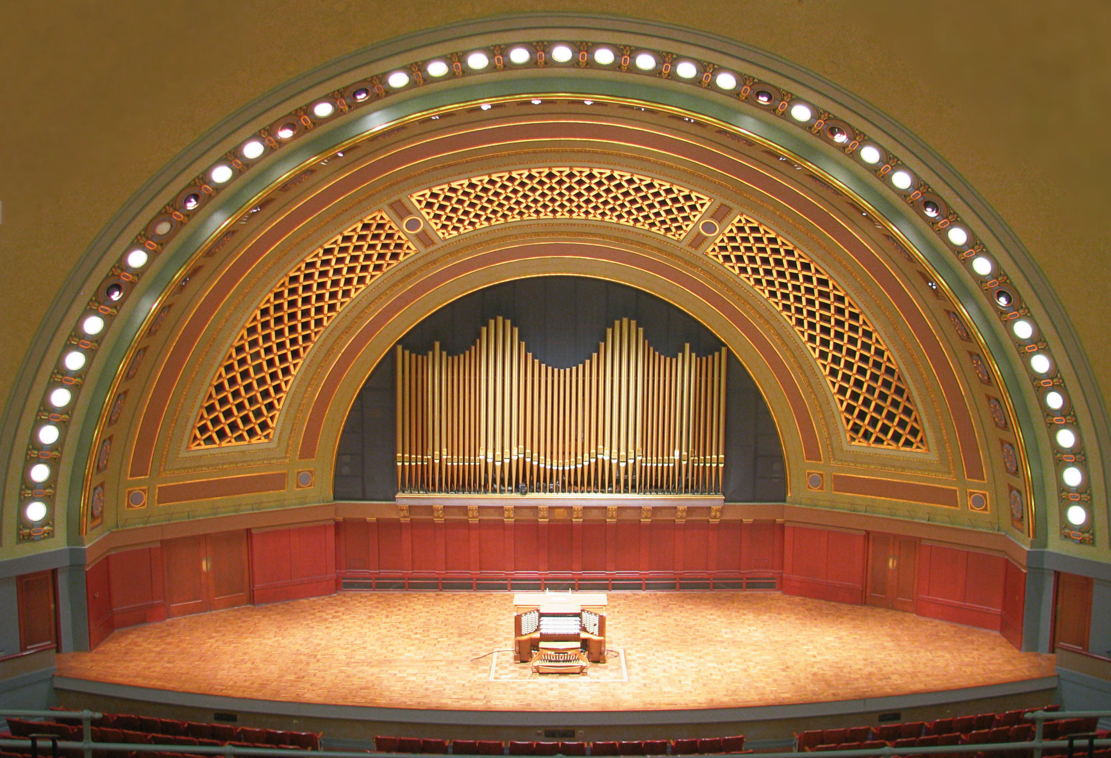
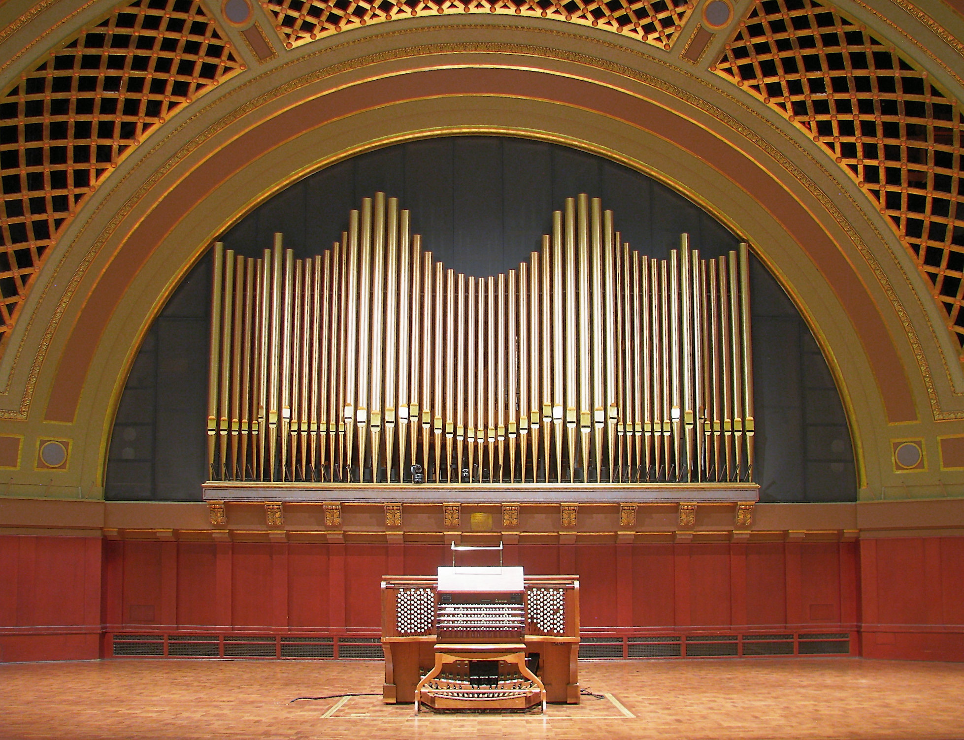
| JPEG | | 11.20 | Pipe organ
|
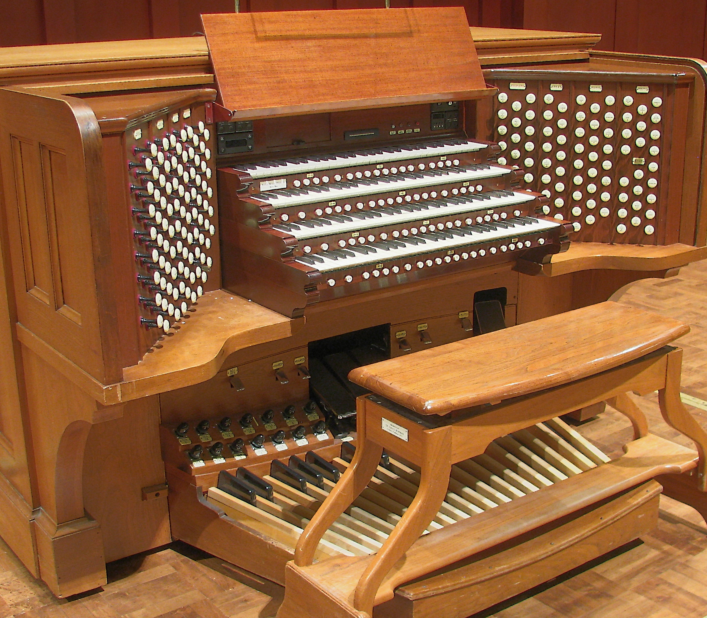
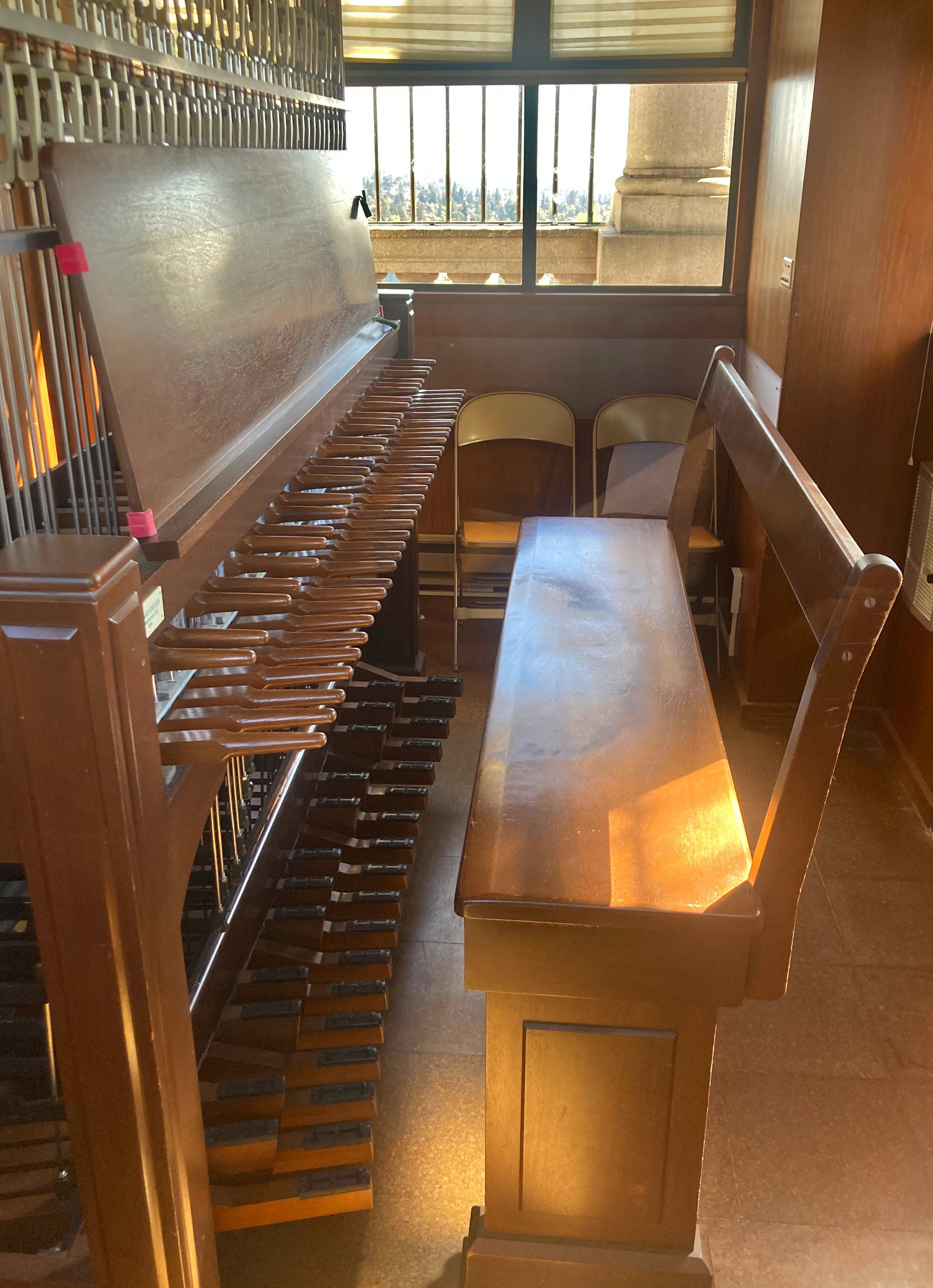
| JPEG | | 11.21 | Organ console
|
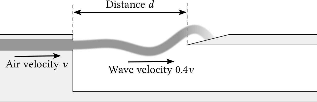
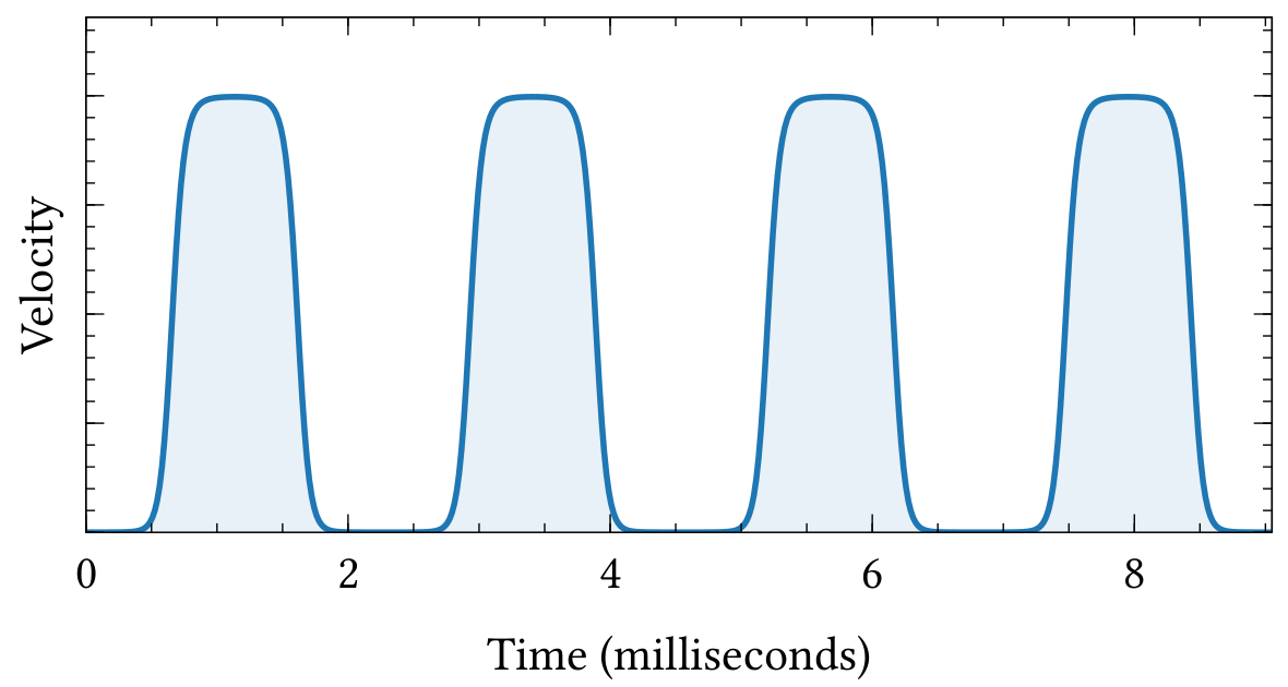
| PDF | PNG | 11.22 | Air velocity of an oscillating jet
|
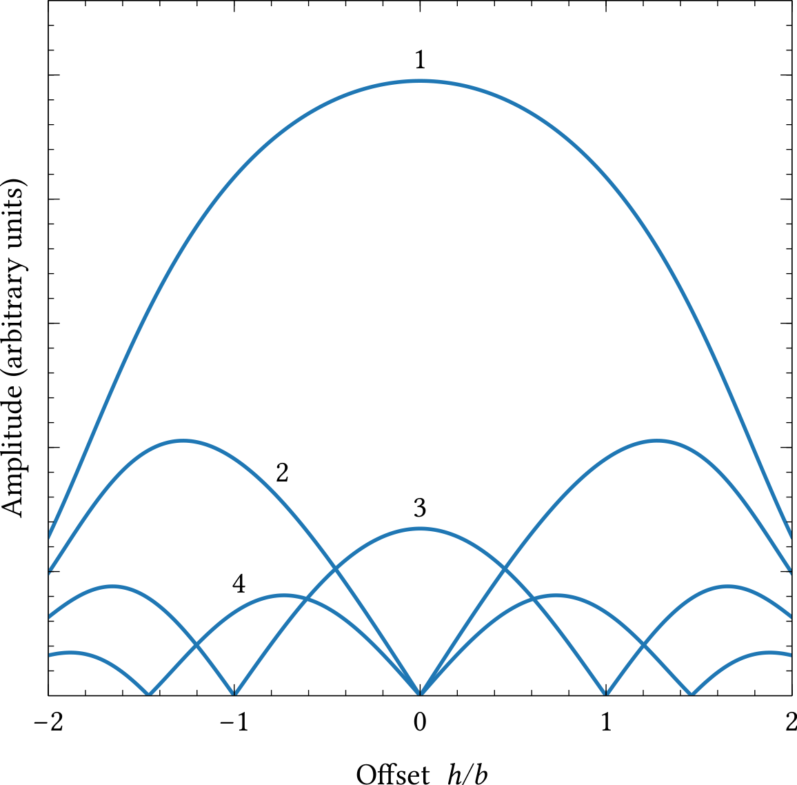
| PDF | PNG | 11.23 | Harmonics generated by an oscillating jet
|
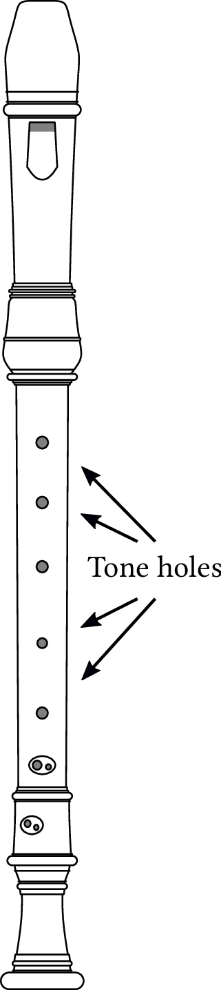
| PDF | PNG | – | Tone holes on a recorder
|
| JPEG | | – | Alto recorder
|
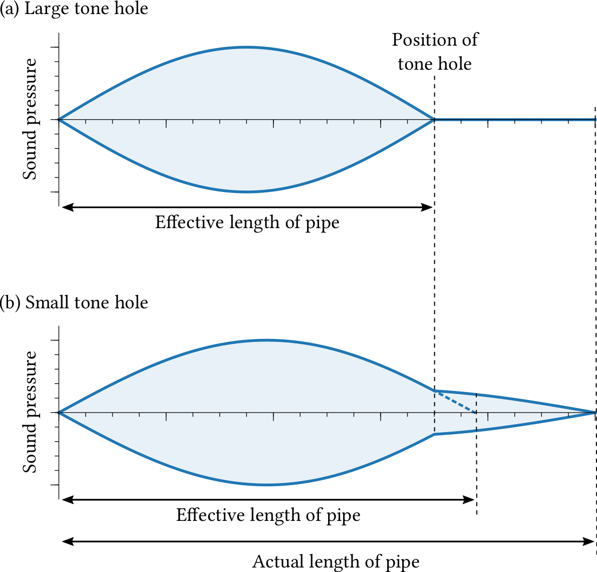
| PDF | PNG | 11.24 | Sound pressure in a pipe with a tone hole
|
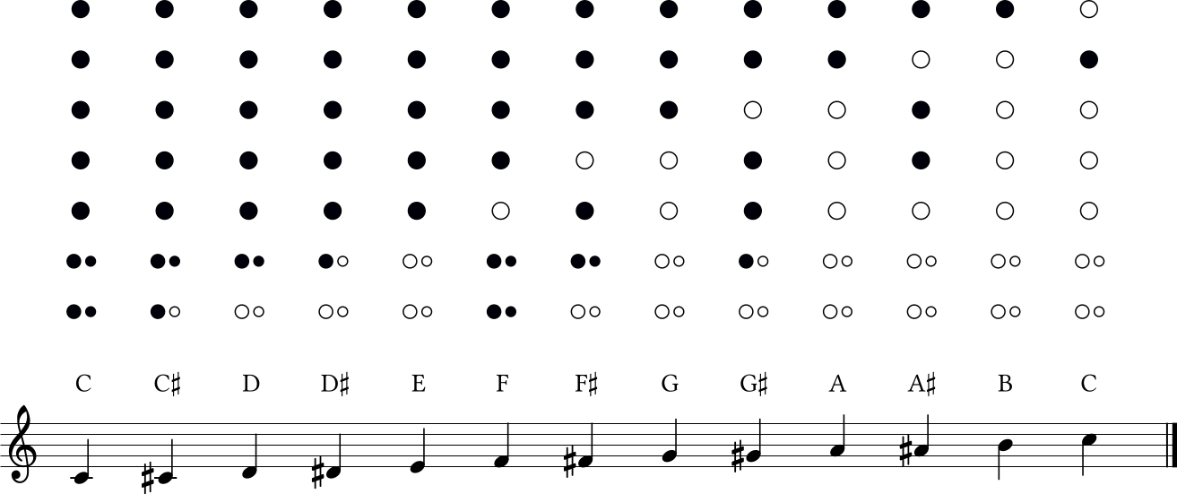
| PDF | PNG | 11.25 | Fingerings on the recorder
|
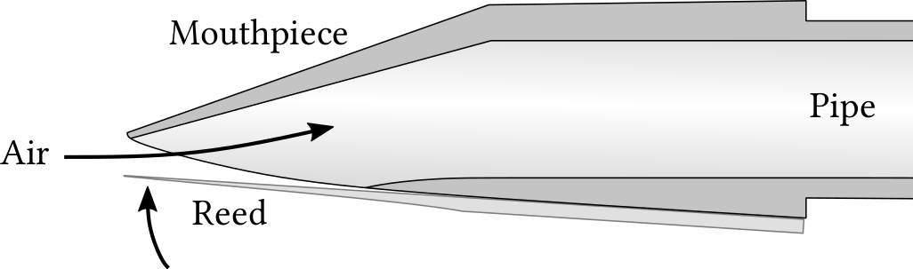
| PDF | PNG | 11.27 | Clarinet mouthpiece
|
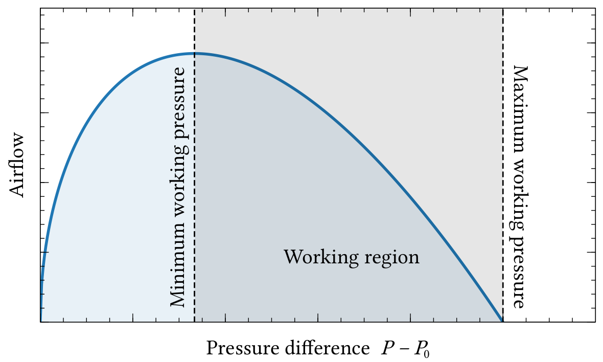
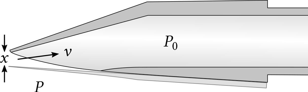
| PDF | PNG | 11.28 | Airflow in a reed instrument
|
| PDF | PNG | – | Clarinet mouthpiece (labeled)
|
| PDF | PNG | 11.30 | The double reed of an oboe
|
| PDF | PNG | 11.31 | Spectra of oboe and saxophone
|
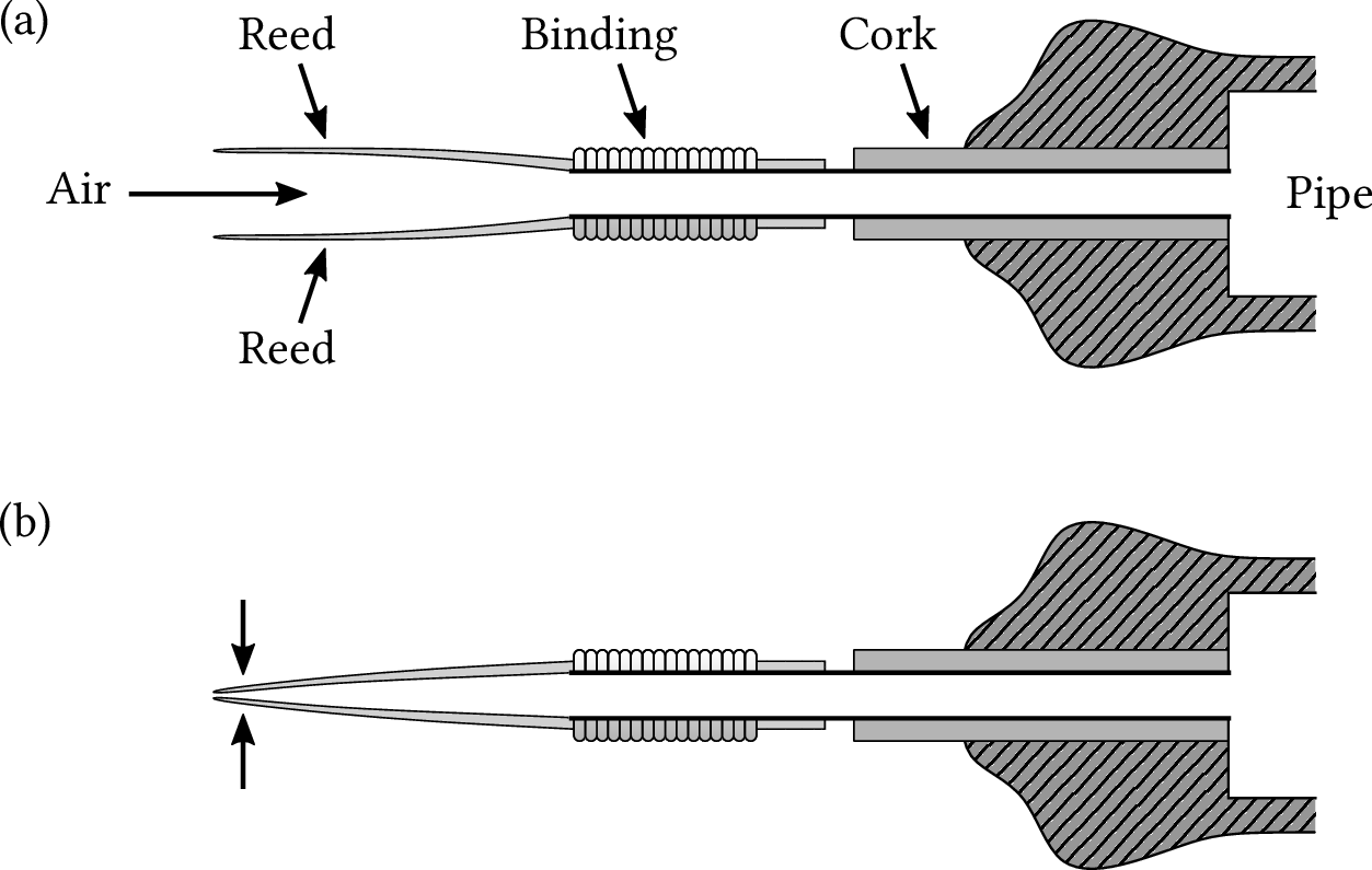
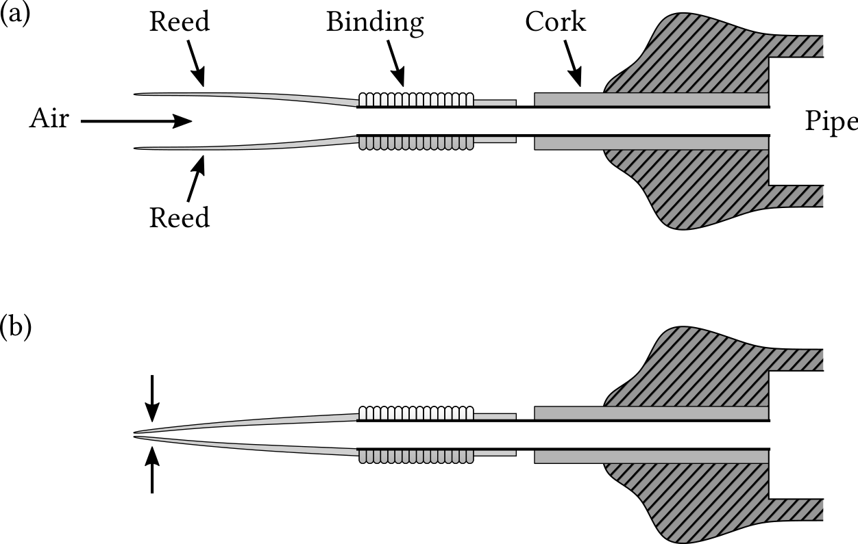
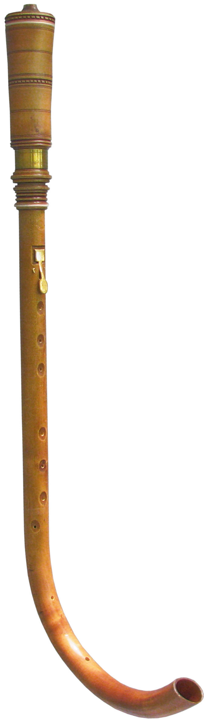
| JPEG | | – | Crumhorn
|
| PDF | PNG | 11.32 | Straight bugle
|
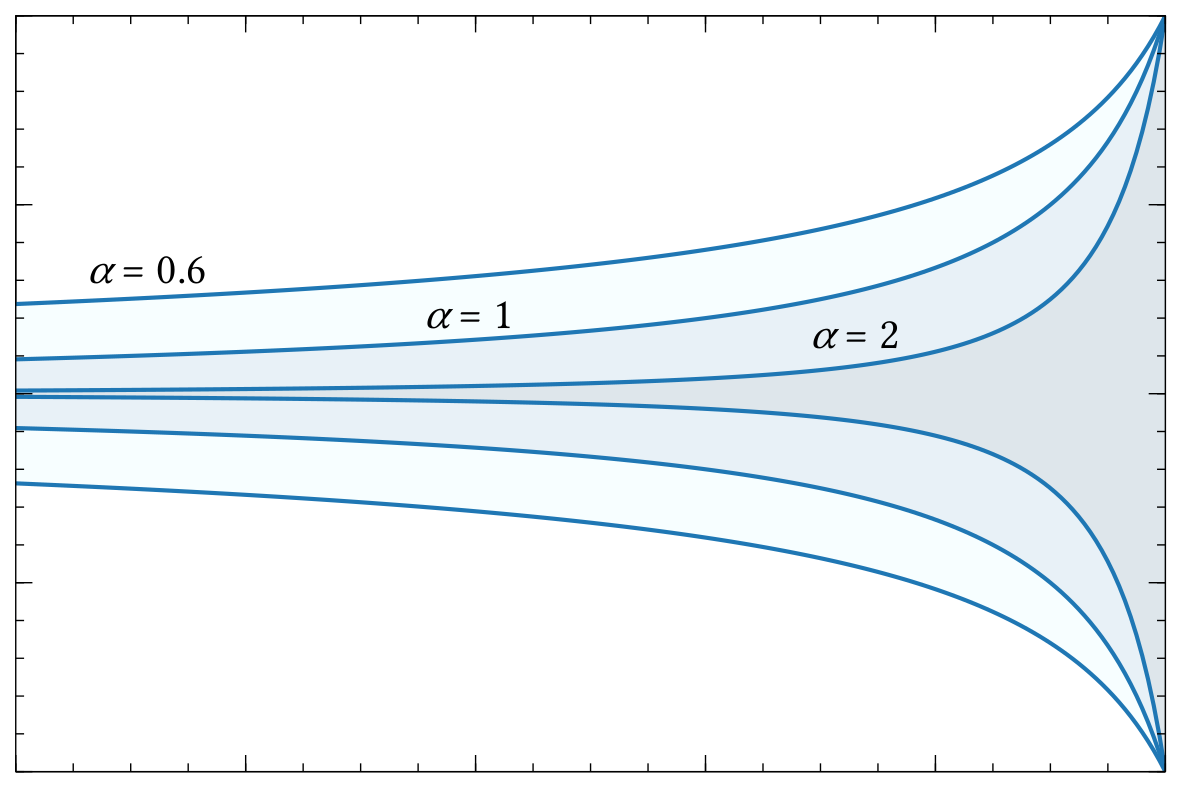
| PDF | PNG | 11.33 | Shapes of Bessel horns
|
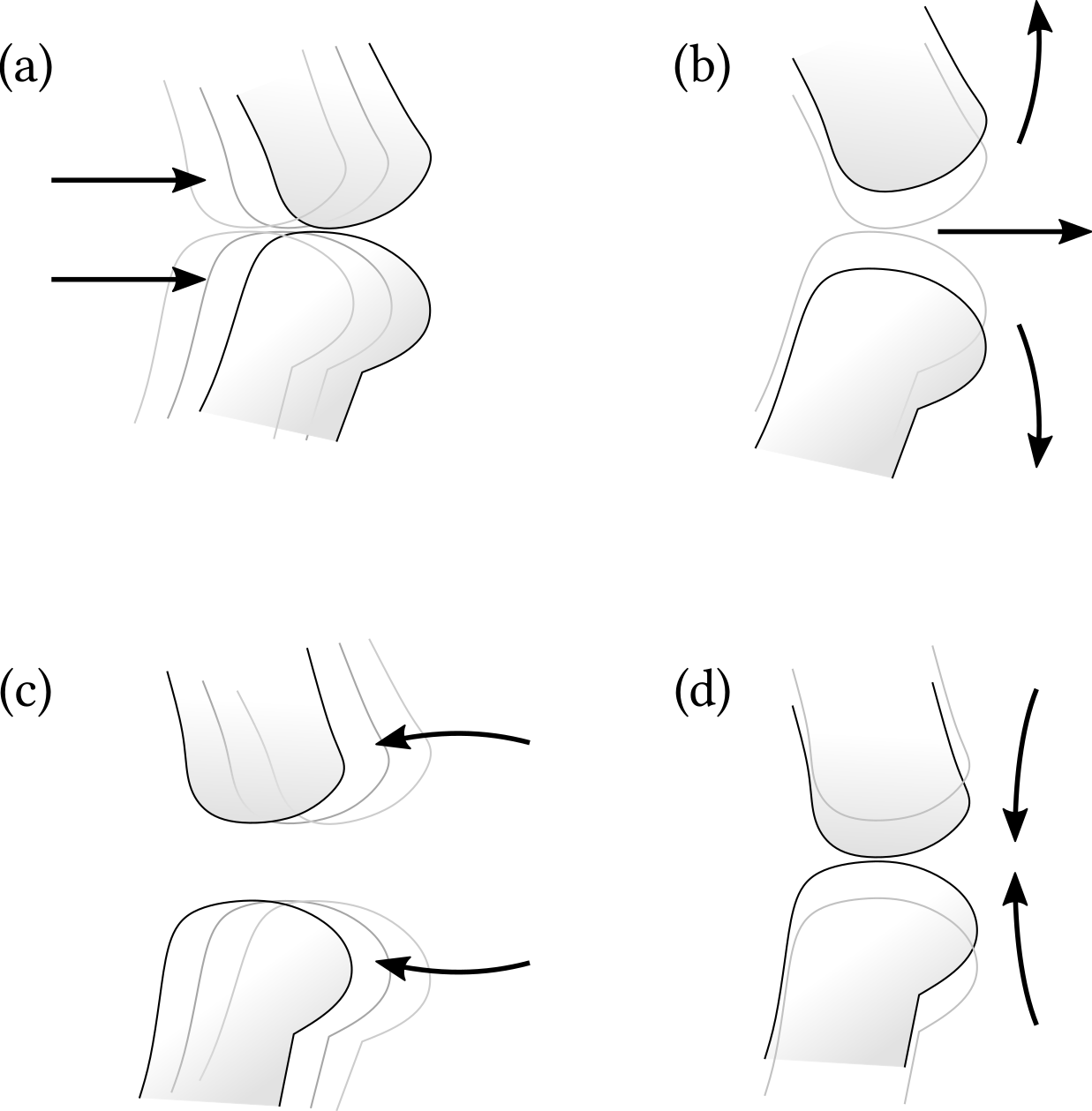
| PDF | PNG | 11.34 | Motion of the lips when playing trumpet
|
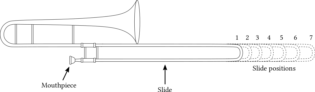
| PDF | PNG | 11.35 | Slide trombone
|
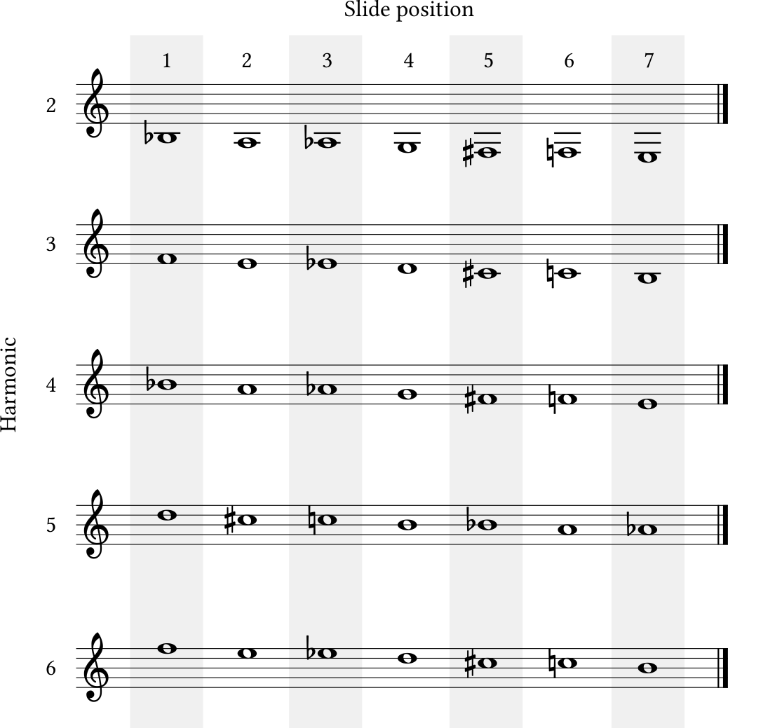
| PDF | PNG | 11.36 | Notes on the tenor trombone
|
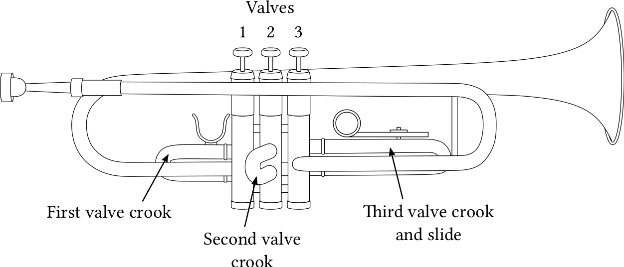
| PDF | PNG | 11.37 | Diagram of a trumpet
|
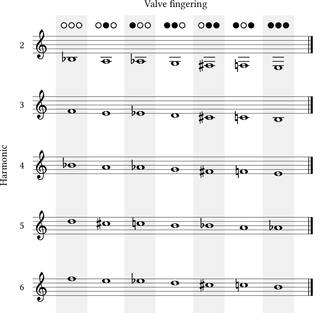
| PDF | PNG | 11.38 | Notes on trumpet
|
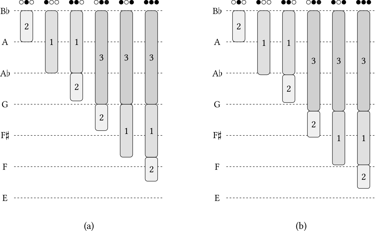
| PDF | PNG | 11.39 | Tuning on the trumpet
|
| JPEG | | – | Harmonica
|
Chapter 12: The voice
| Format | Figure | Description | Credit |
|---|
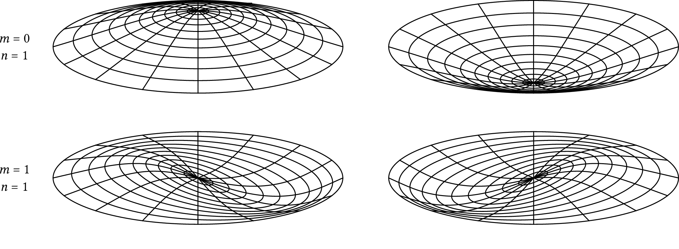
| PDF | PNG | 12.1 | Vibration modes | John Megahan
|
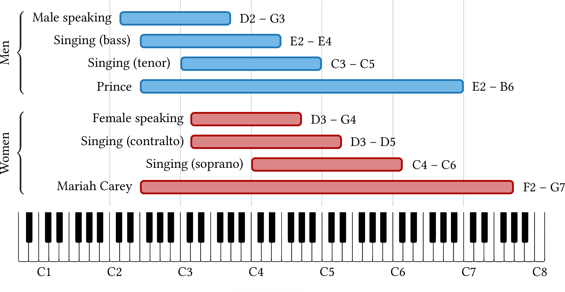
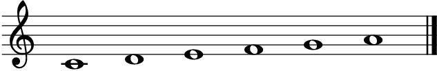
| PDF | PNG | 12.2 | Vocal ranges
|
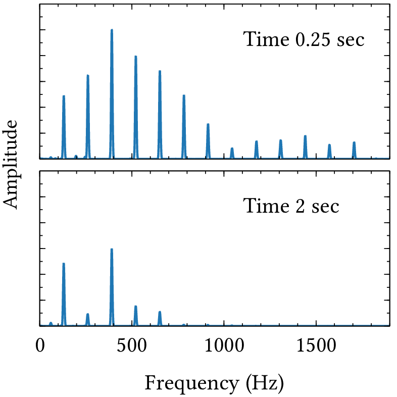
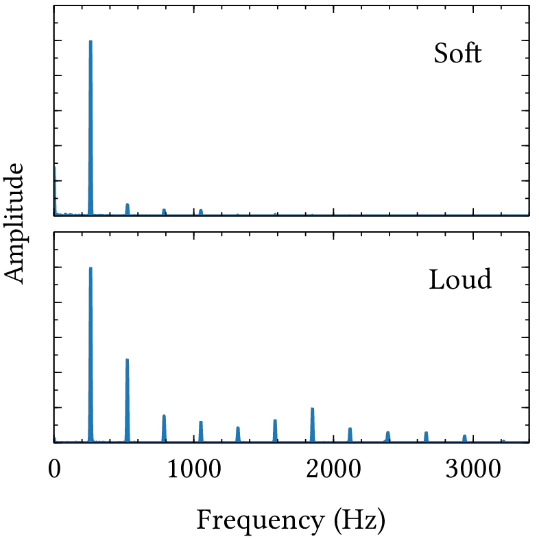
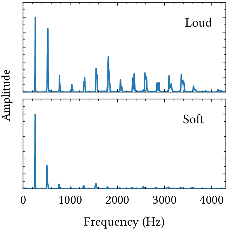
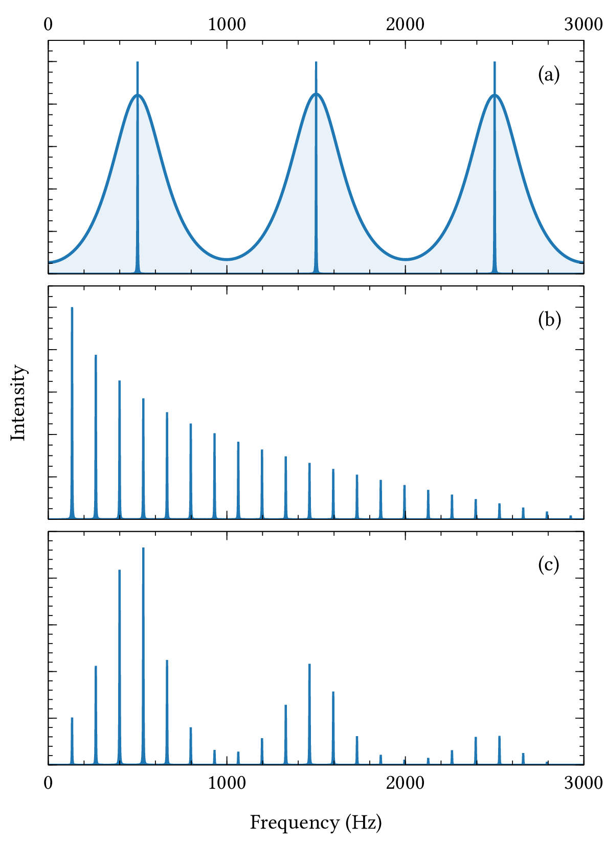
| PDF | PNG | 12.3 | Harmonics of loud and soft notes
|
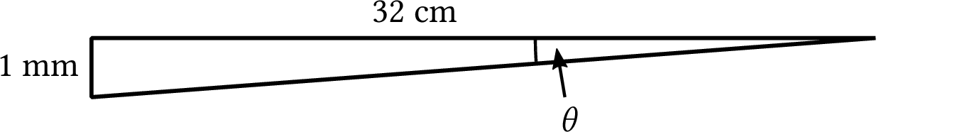
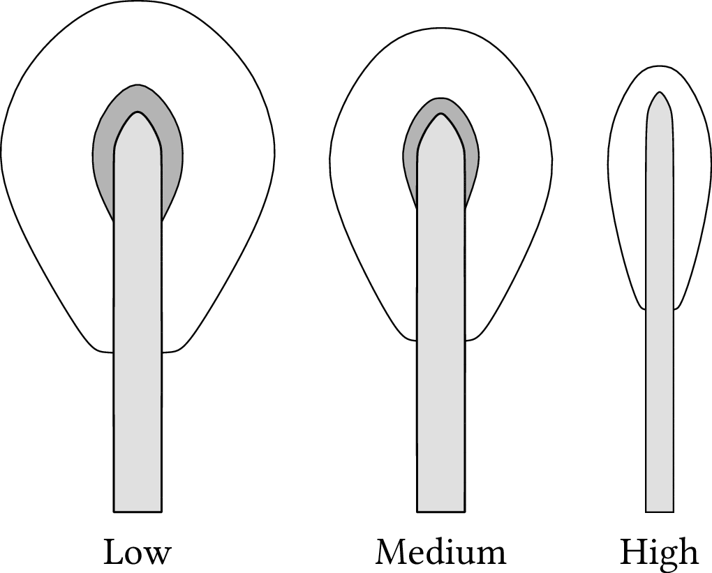
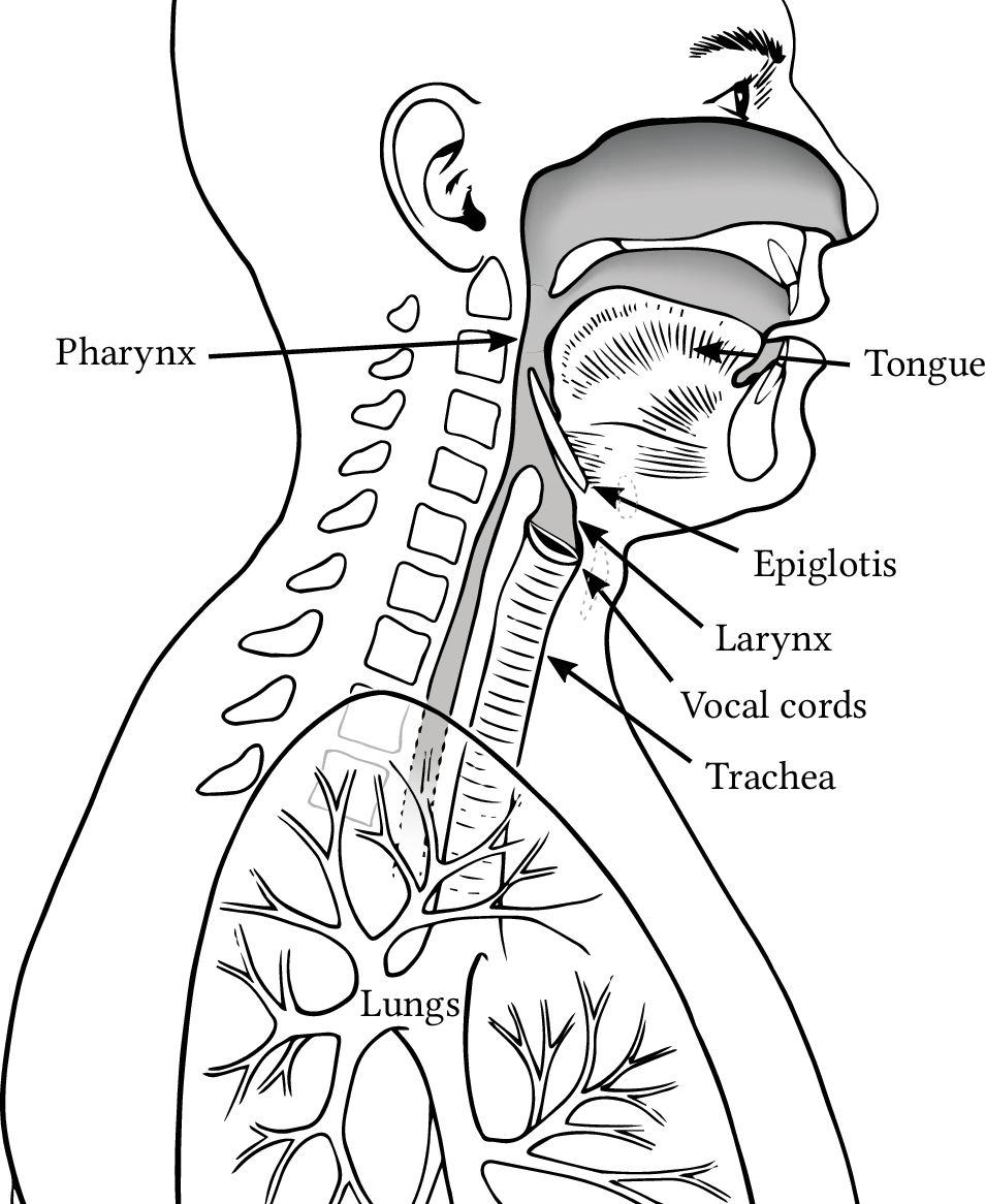
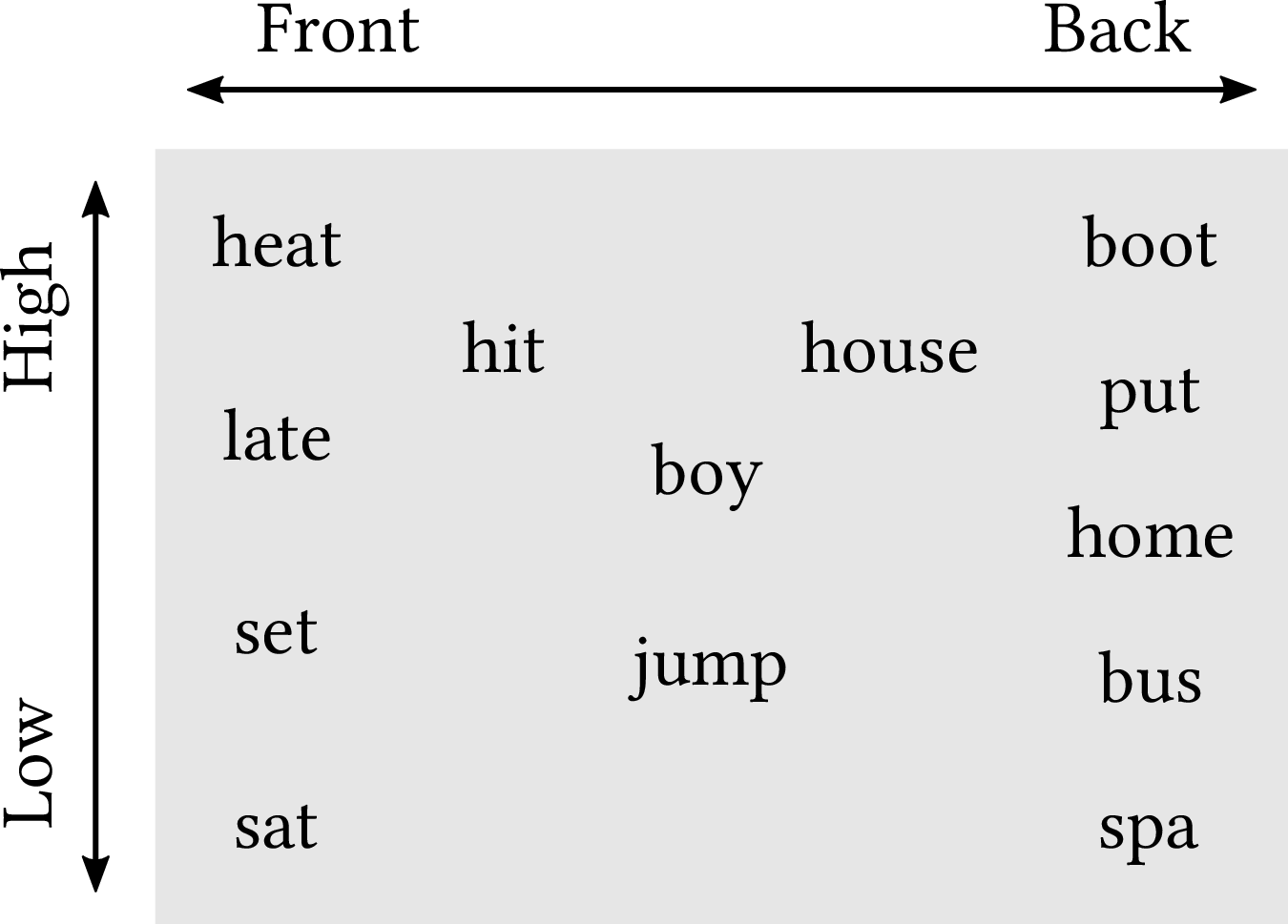
| PDF | PNG | 12.4 | Tongue placement
|
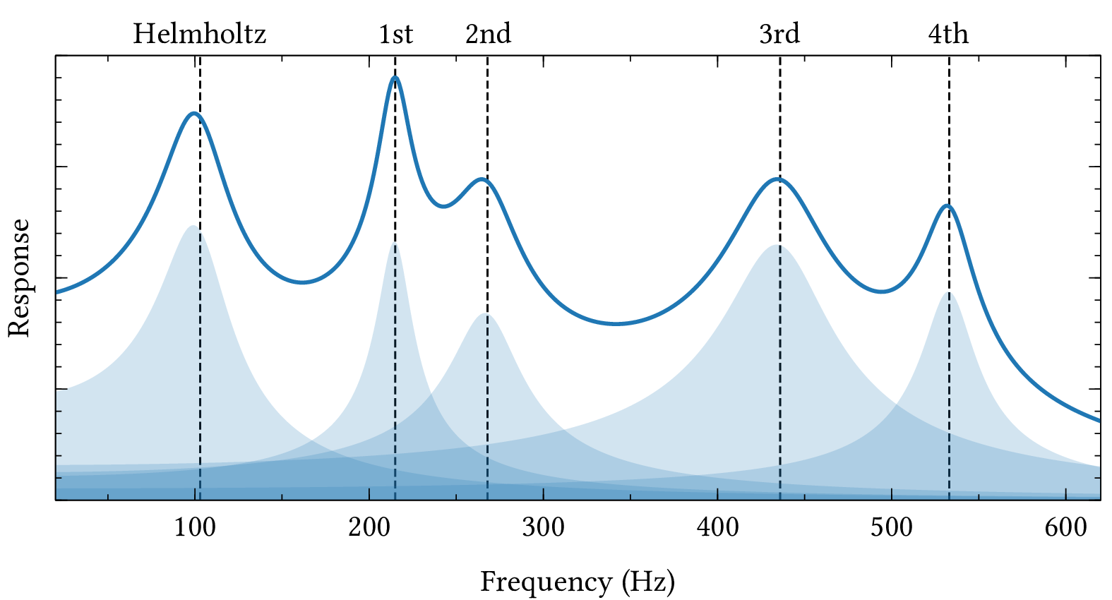
| PDF | PNG | 12.5 | Formants
|
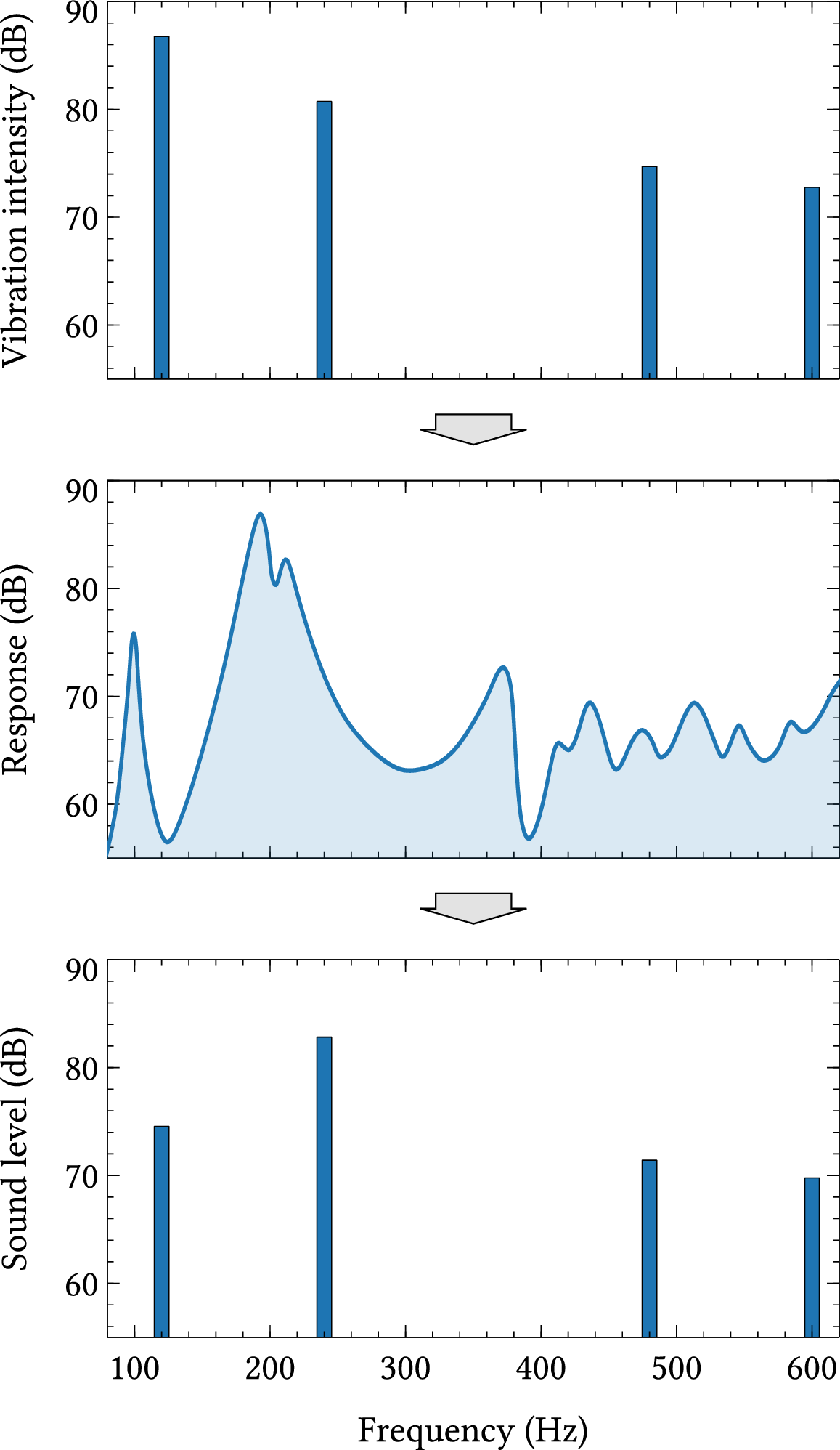
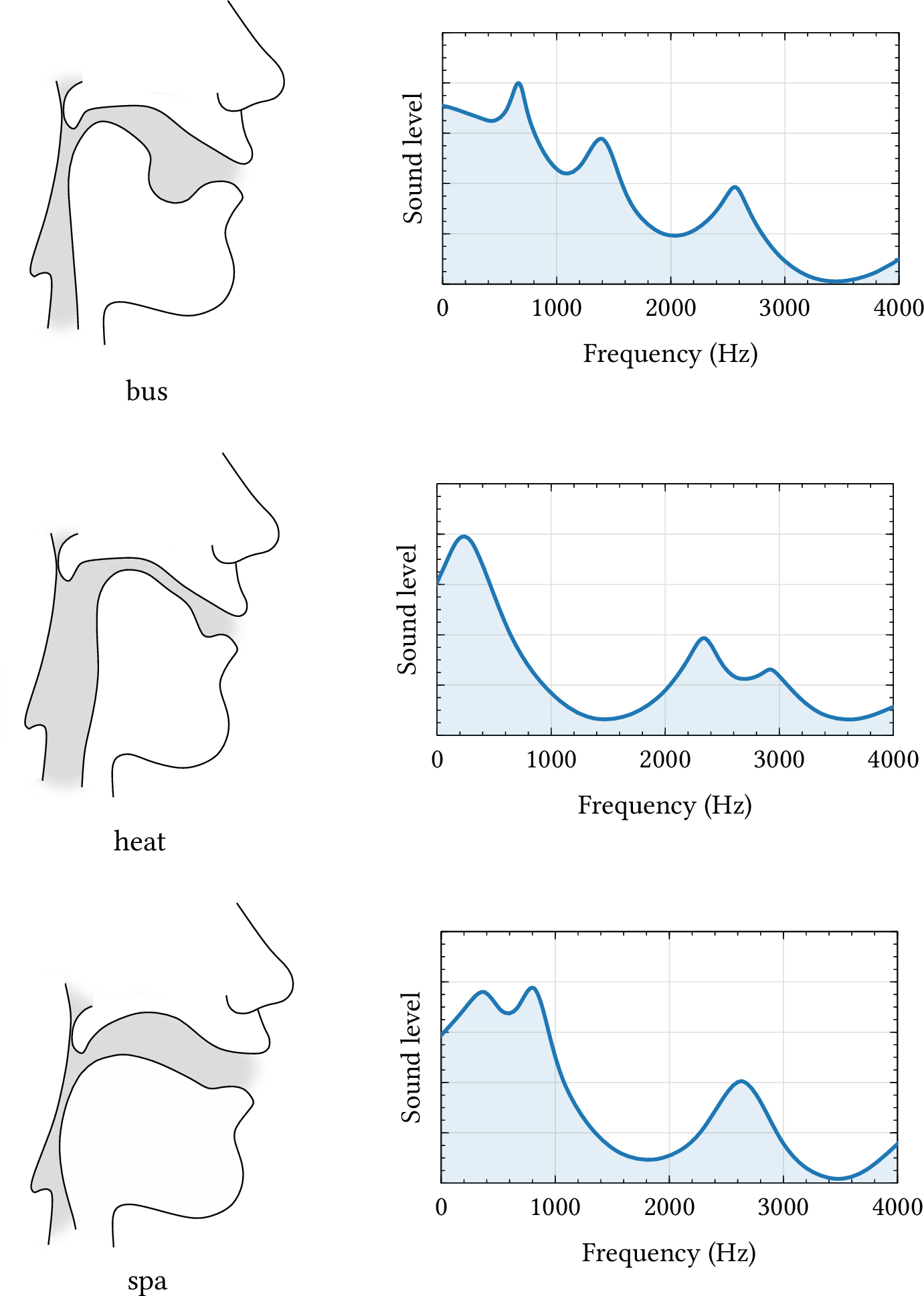
| PDF | PNG | 12.6 | Creation of formants
|
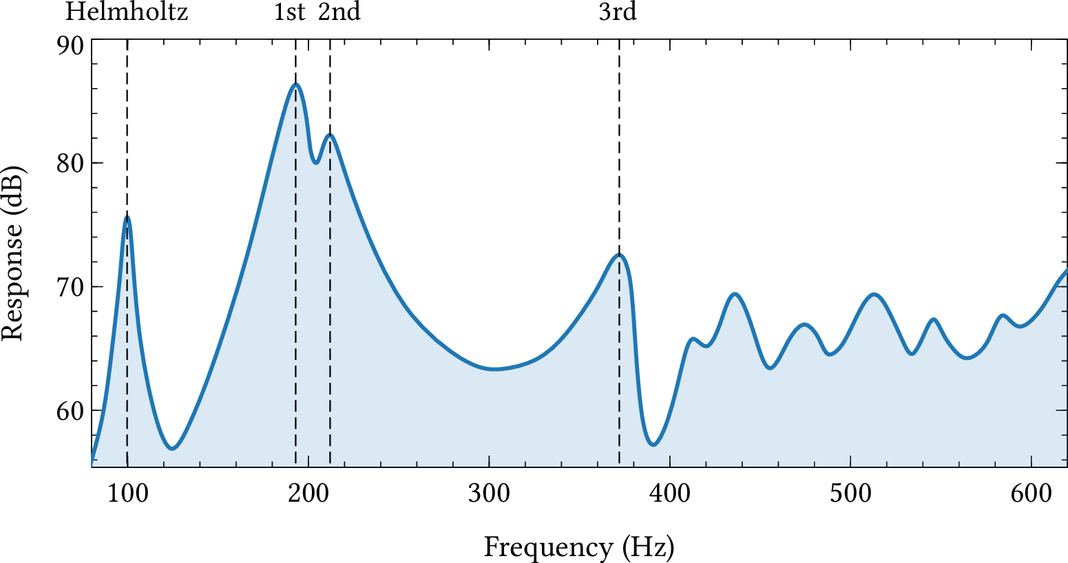
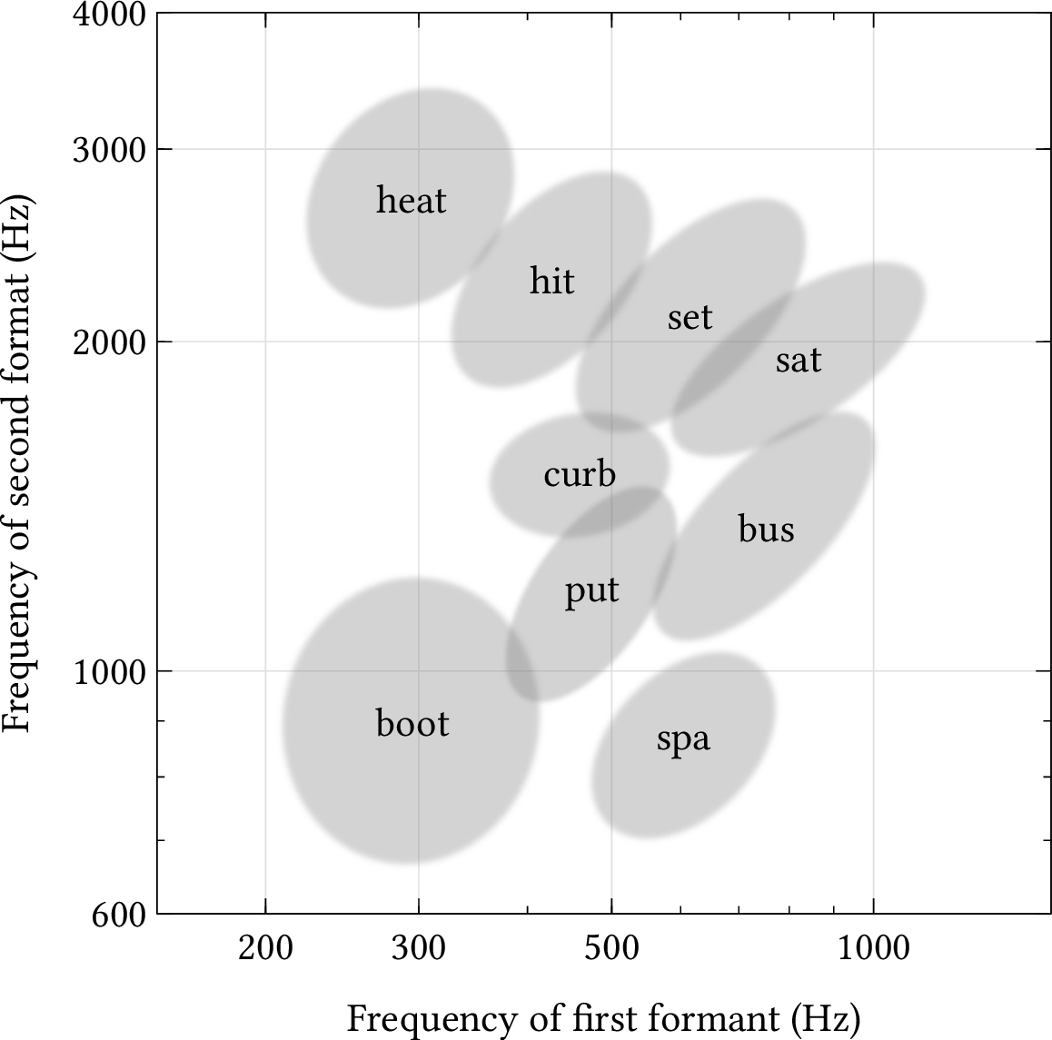
| PDF | PNG | 12.7 | Formant frequencies
|
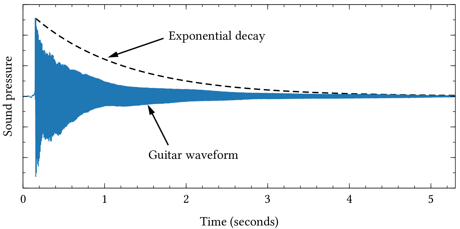
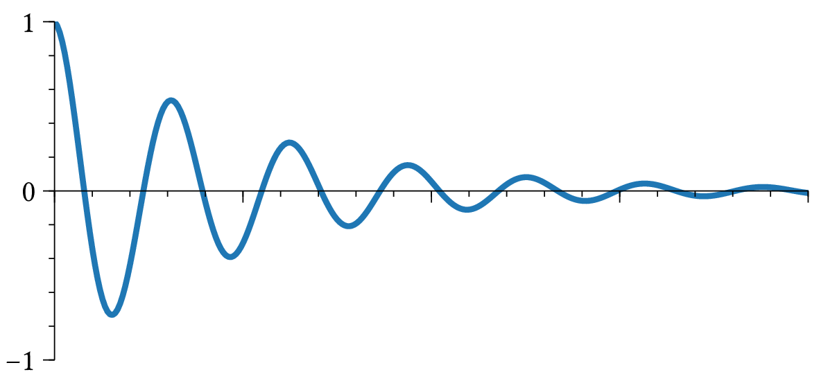
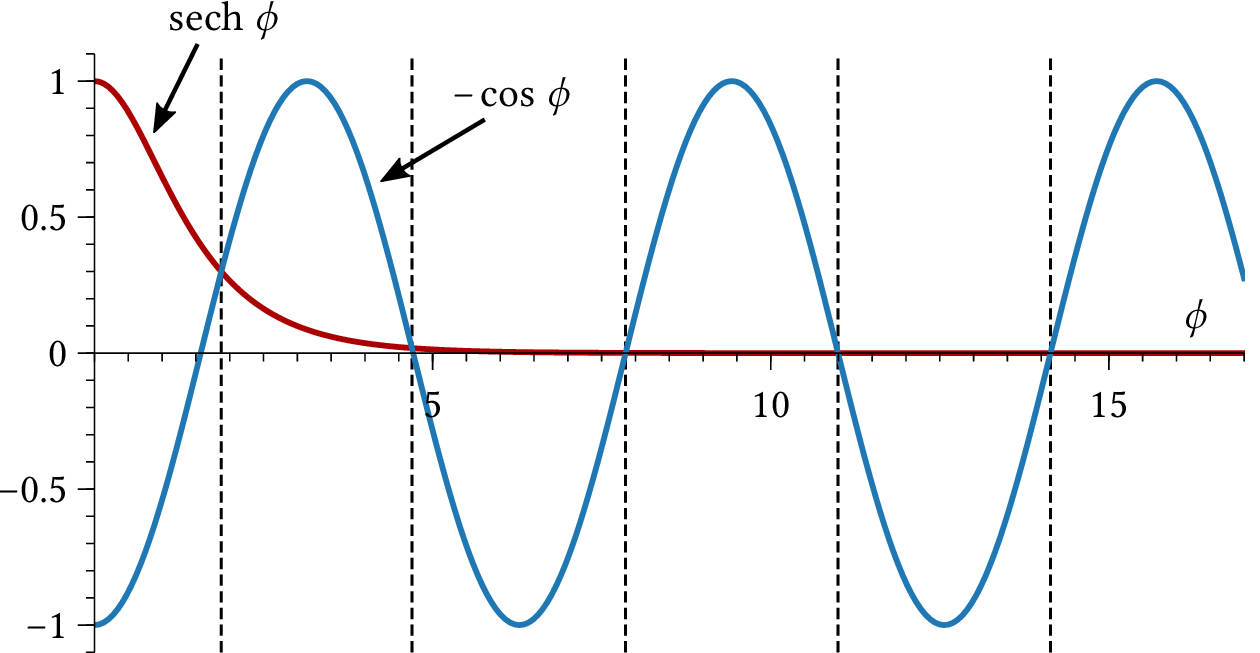
| PDF | PNG | – | Damped sine wave
|
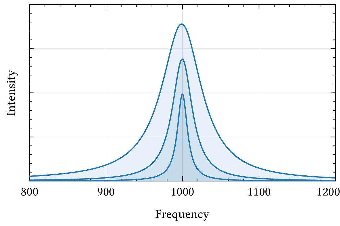
| PDF | PNG | 12.8 | Broad resonance peaks
|
Chapter 13: Percussion
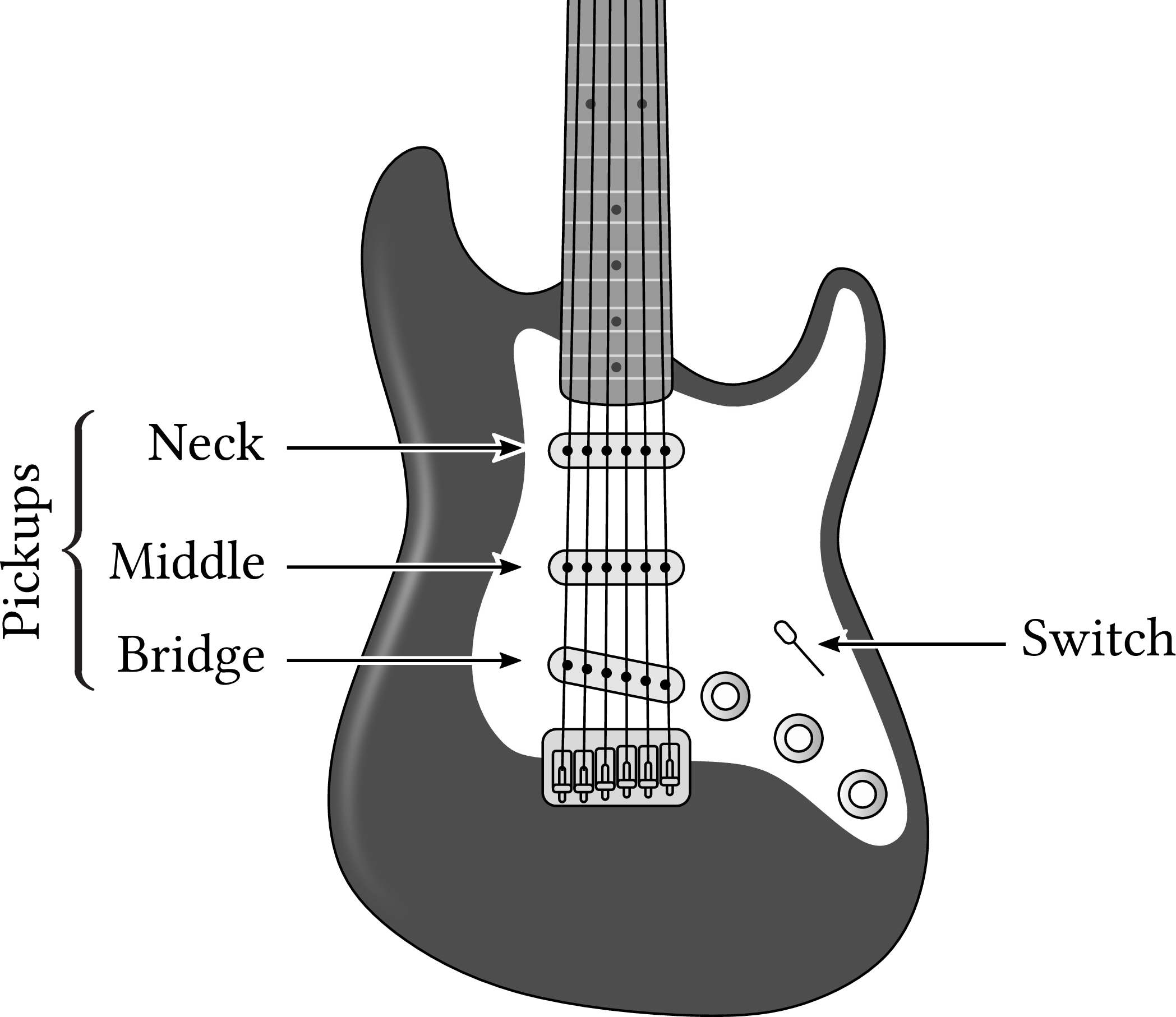
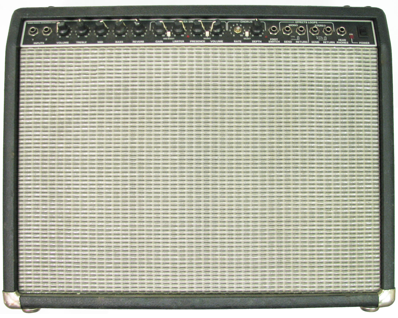
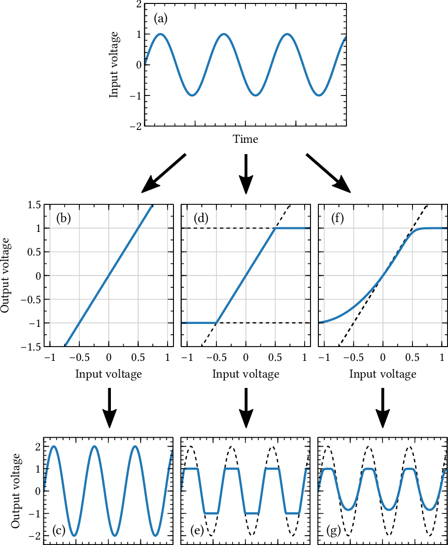
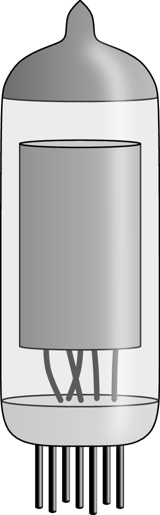
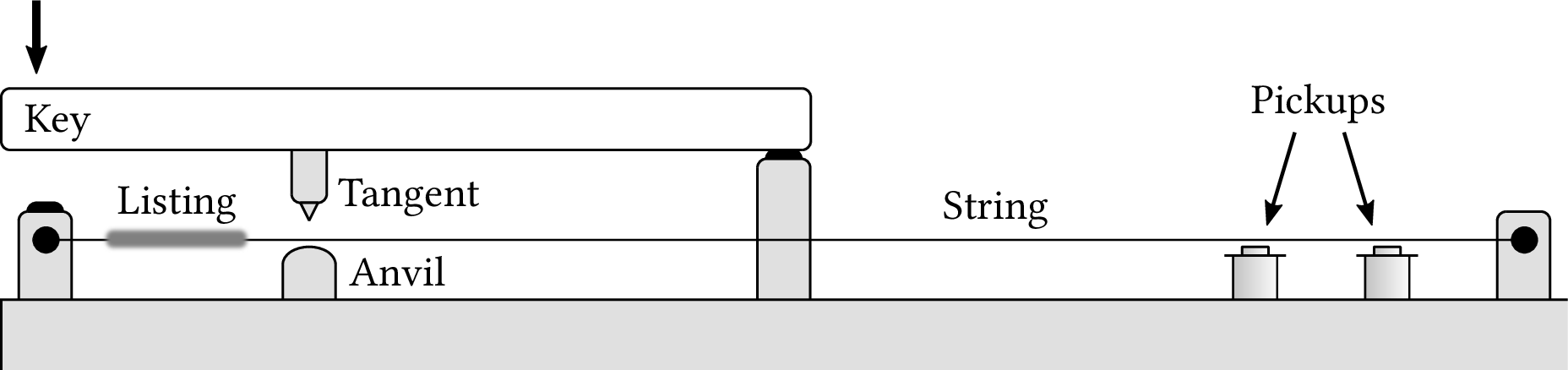
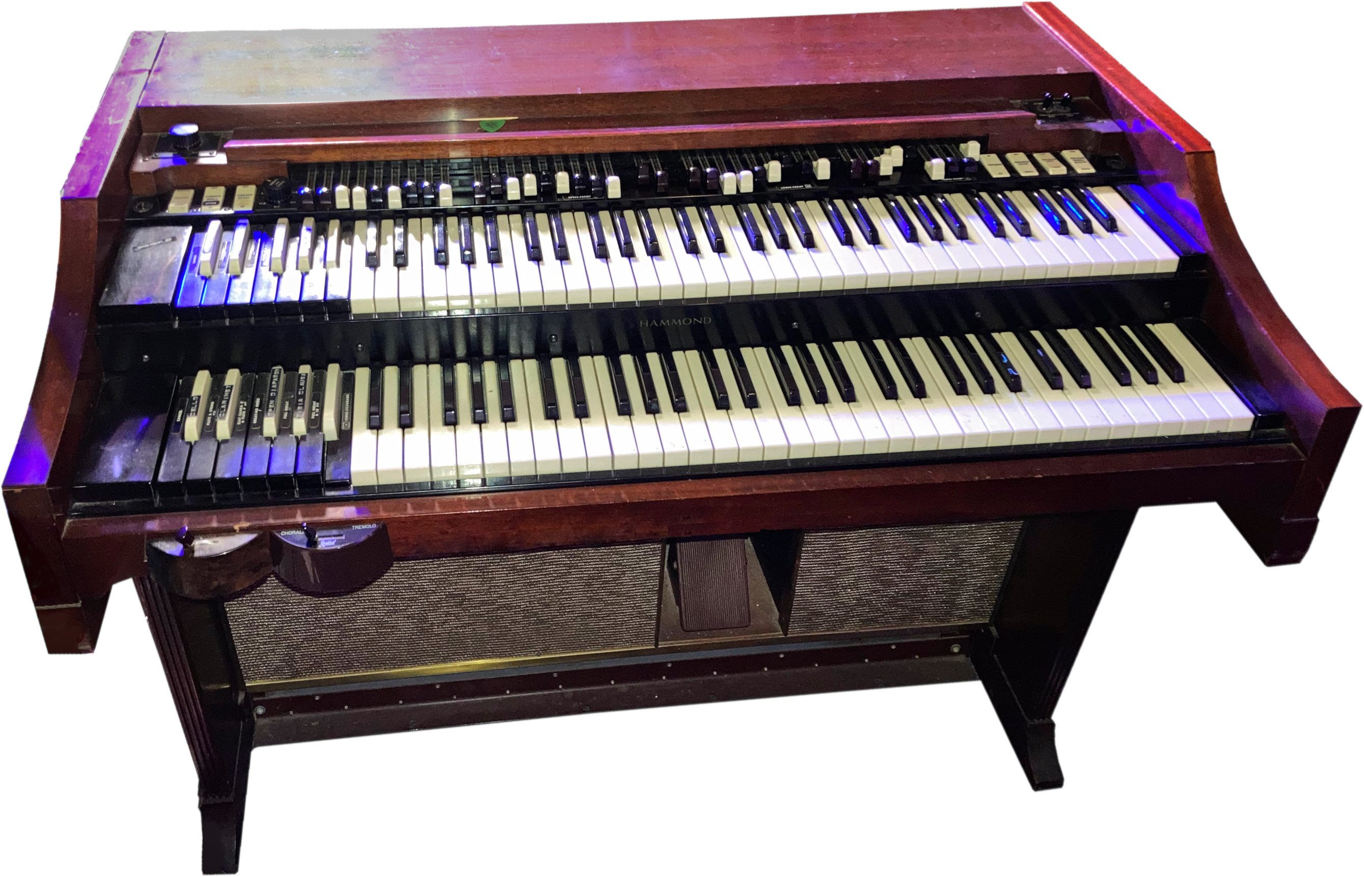
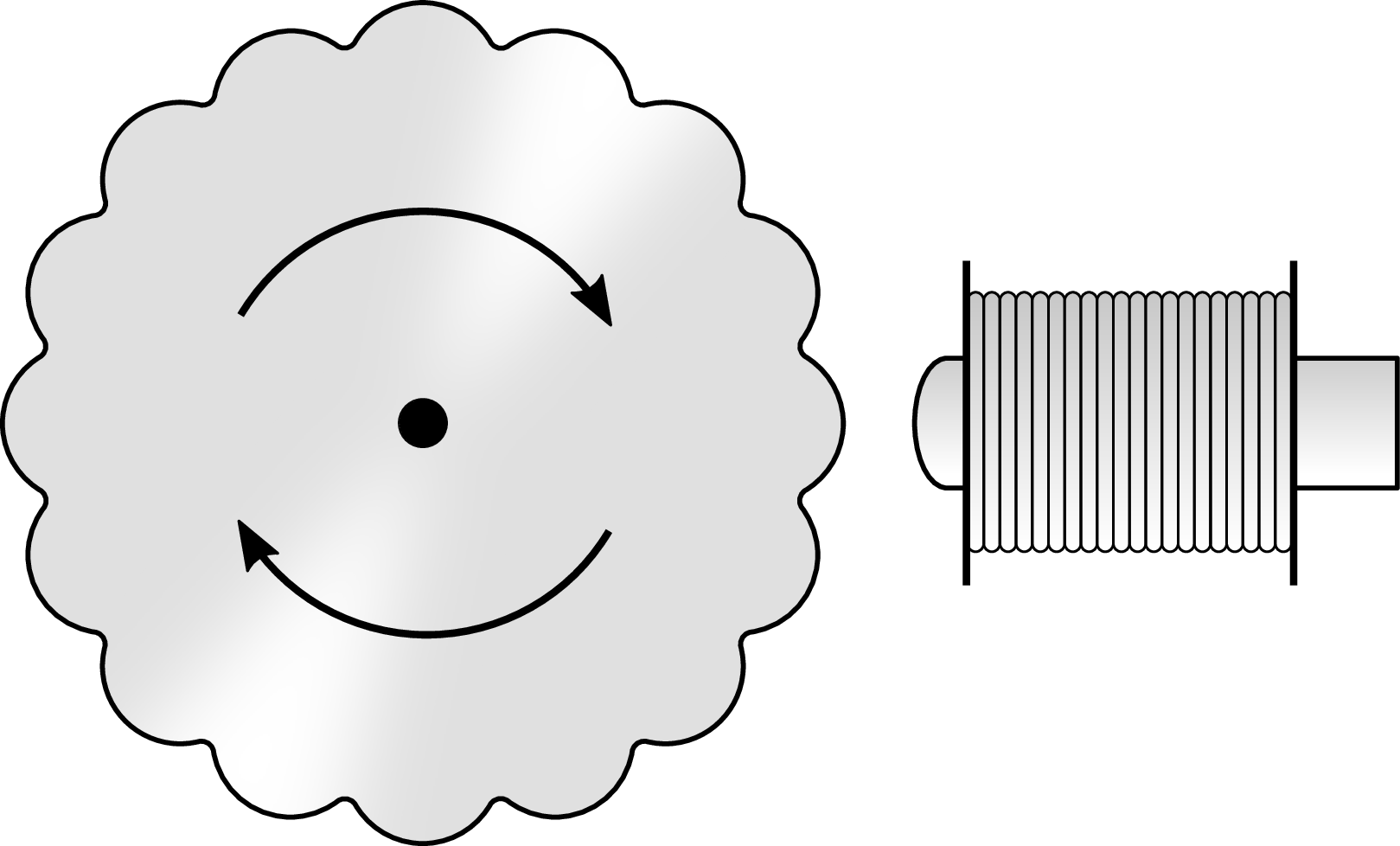
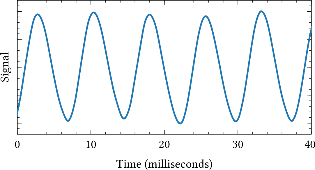
Chapter 14: Electric instruments and the electric guitar
Chapter 15: Electronic instruments and synthesizers
| Format | Figure | Description |
|---|
| PDF | PNG | 15.1 | Oscillator circuit
|
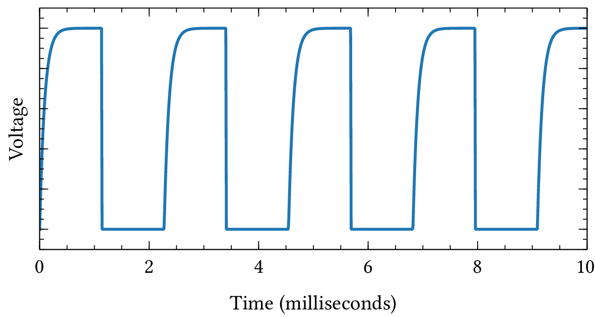
| PDF | PNG | 15.2 | Oscillator waveform
|
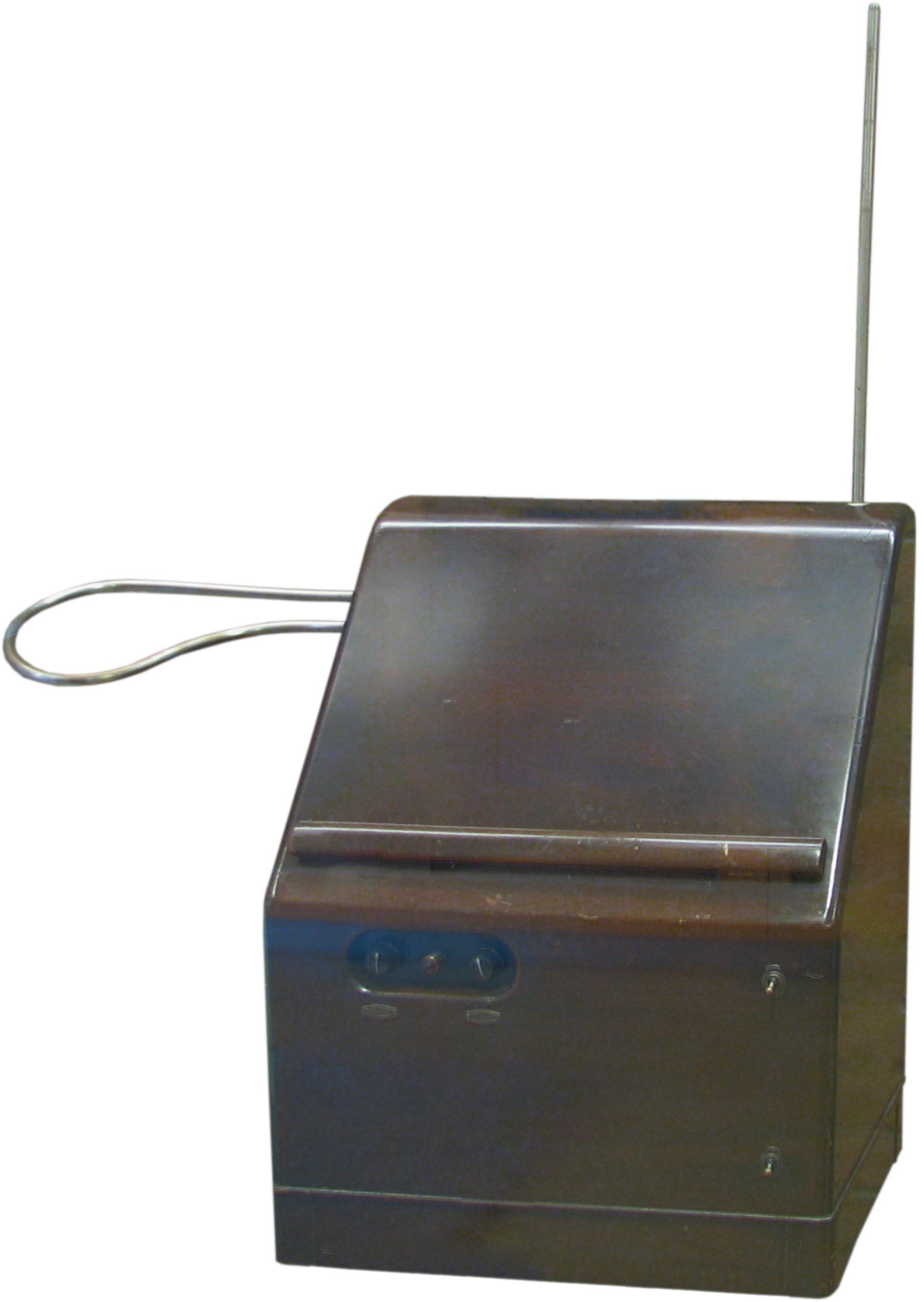
| JPEG | | 15.3 | Theremin
|
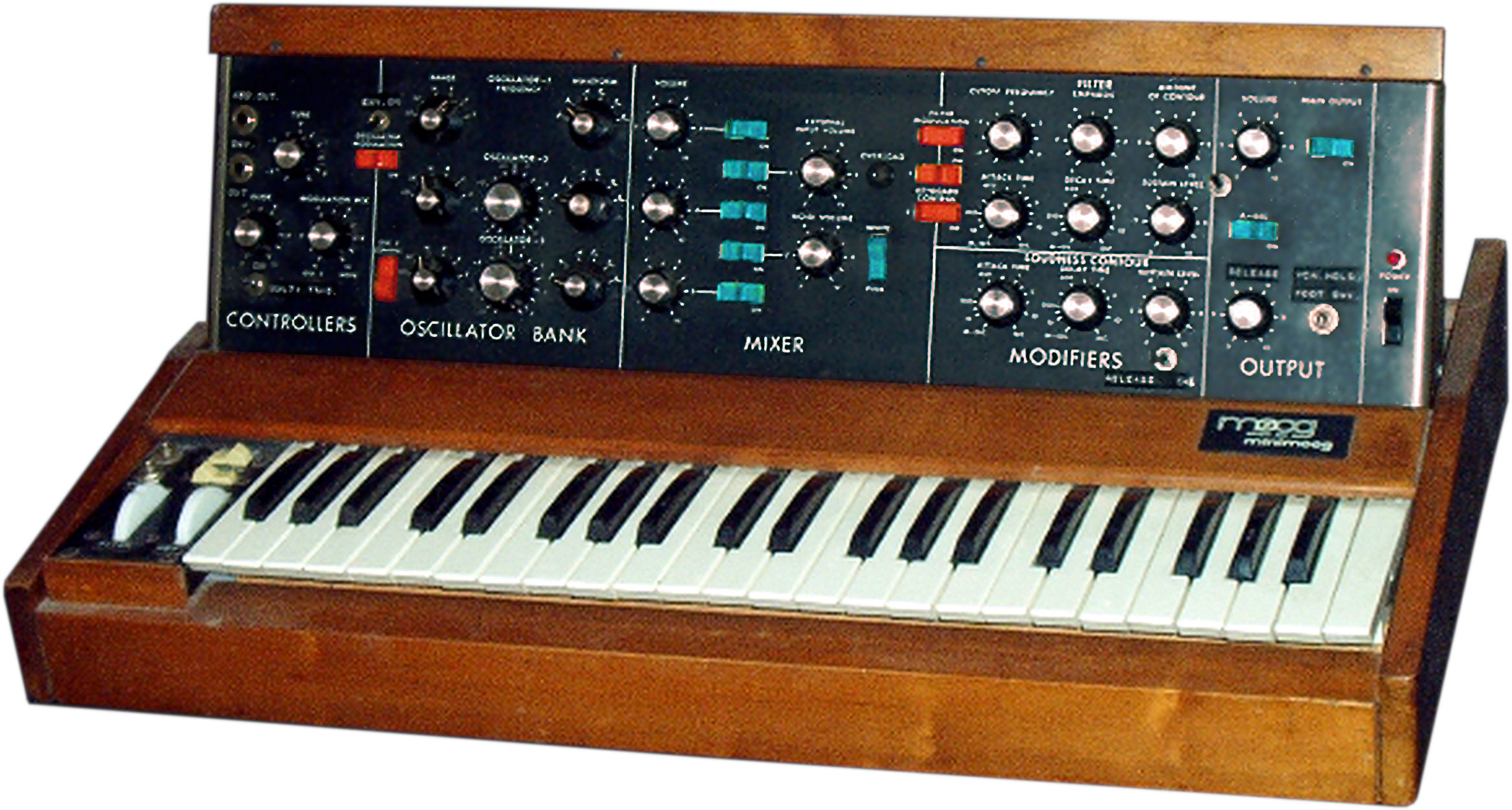
| JPEG | | 15.4 | Moog synthesizer
|
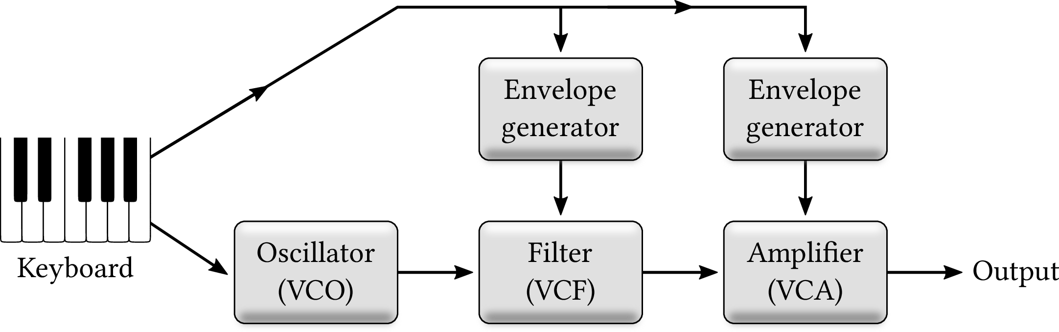
| PDF | PNG | 15.5 | Synthesizer schematic
|
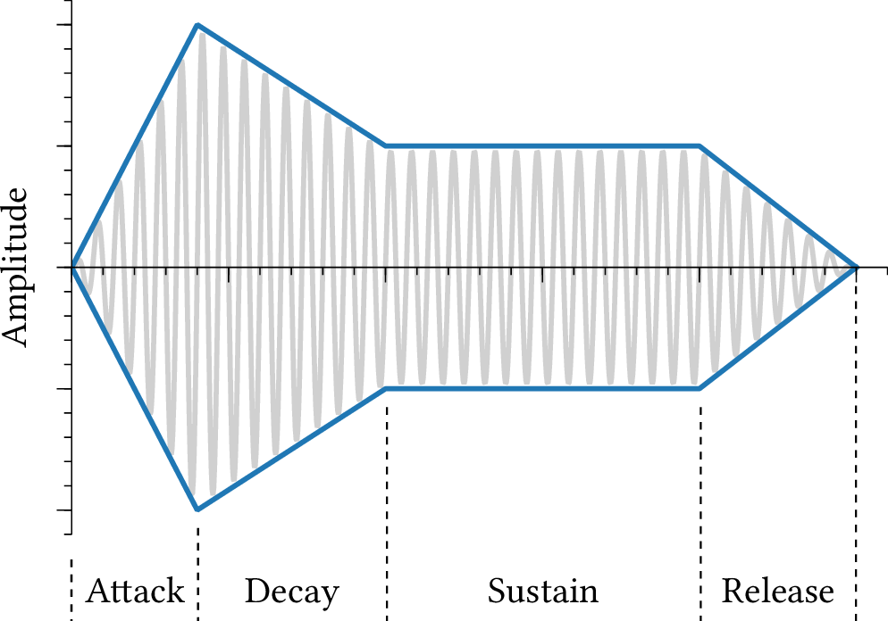
| PDF | PNG | 15.6 | Amplitude envelope
|
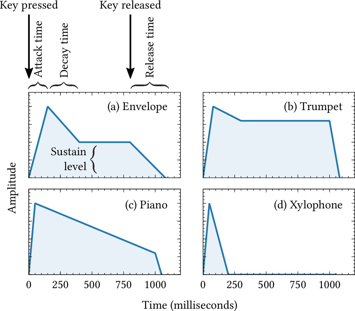
| PDF | PNG | 15.7 | Example envelopes
|
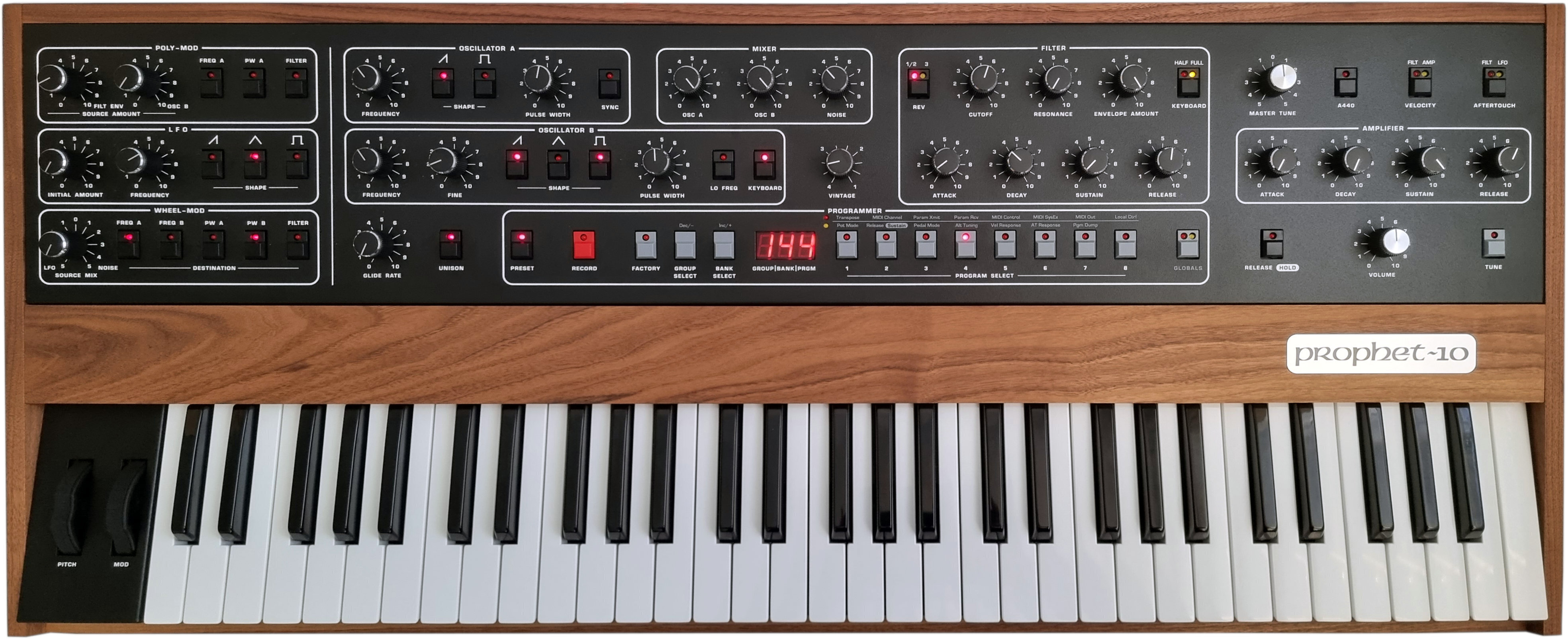
| JPEG | | 15.8 | Prophet-10 synthesizer
|
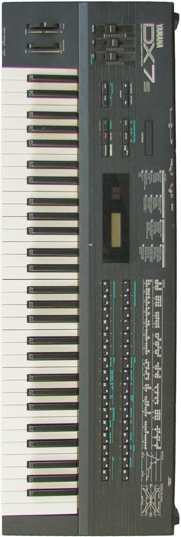
| JPEG | | – | Yamaha DX7
|
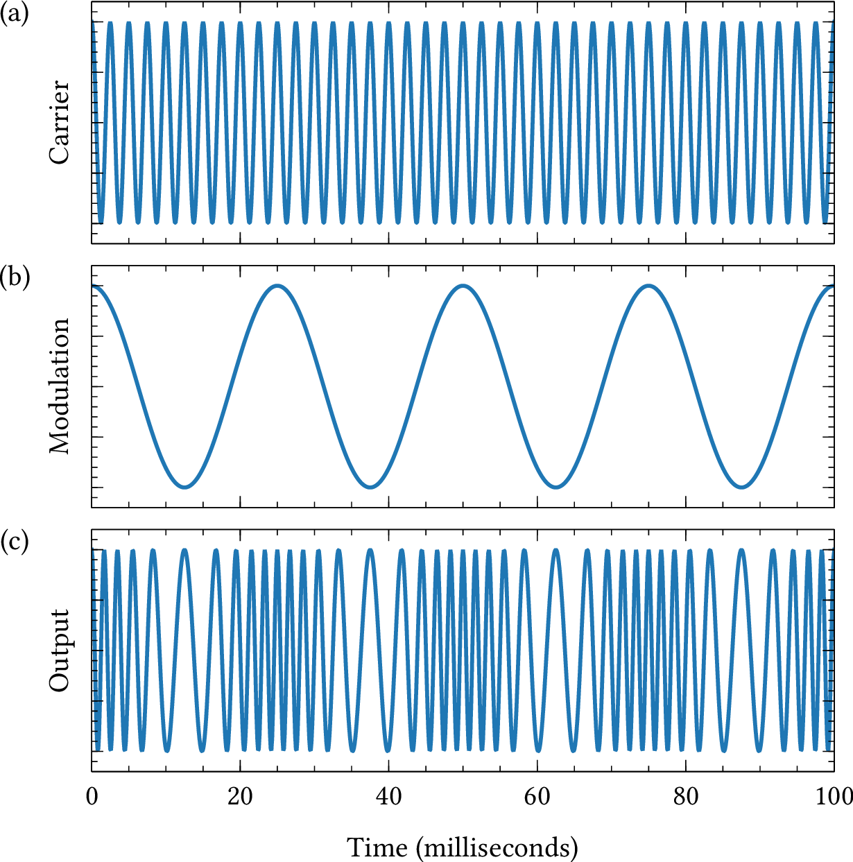
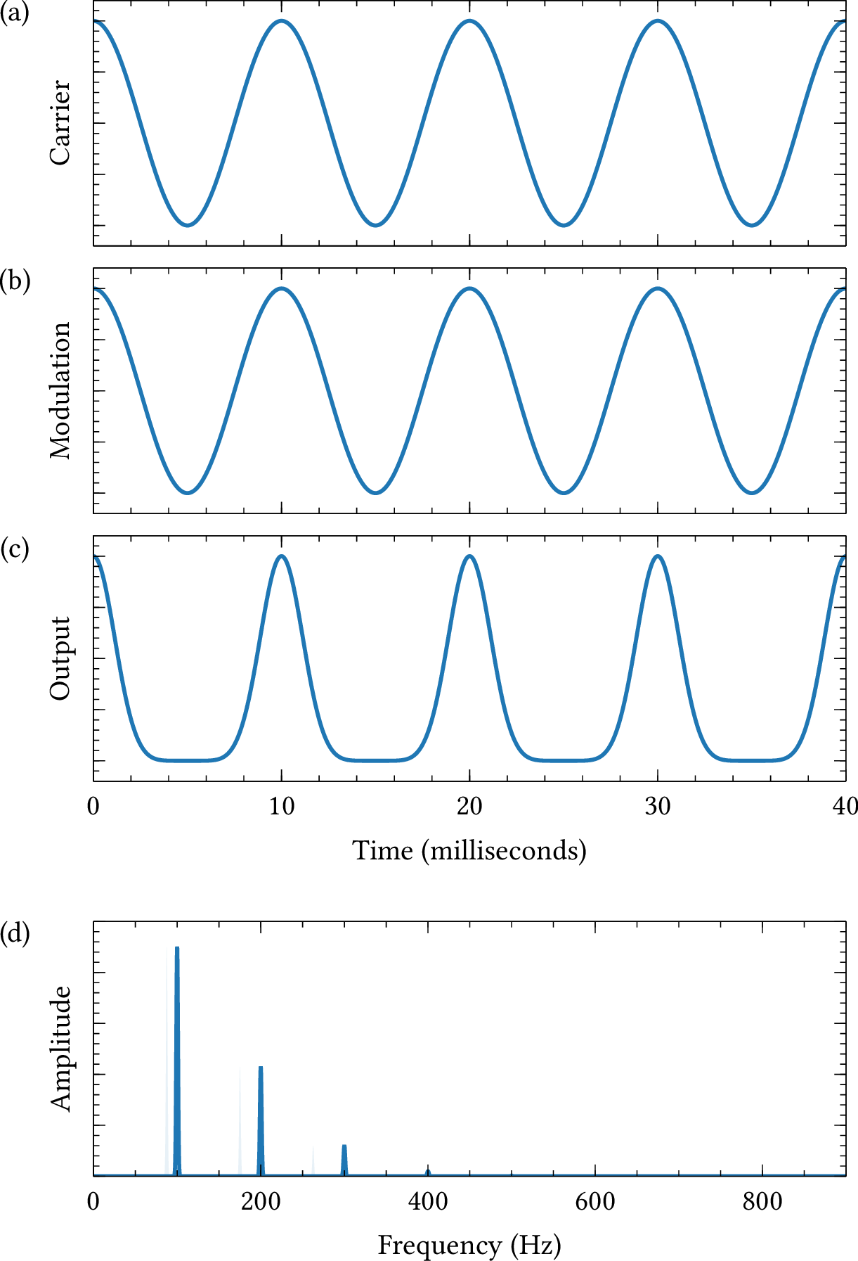
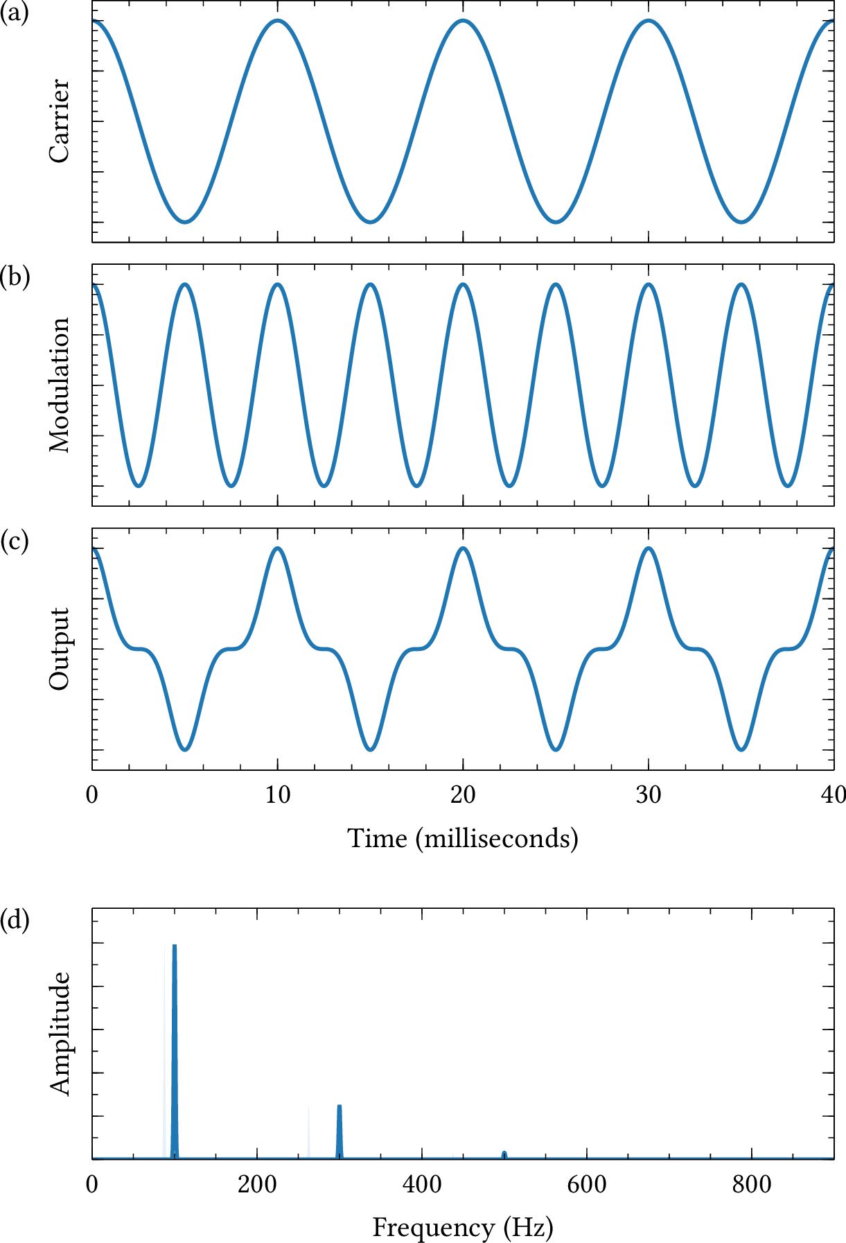
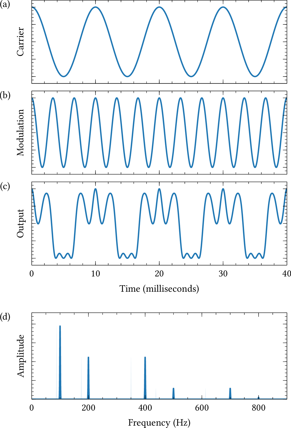
| PDF | PNG | 15.9 | Frequency modulation
|
| PDF | PNG | 15.10 | Frequency modulation
|
| PDF | PNG | 15.11 | Frequency modulation
|
| PDF | PNG | 15.12 | Frequency modulation
|
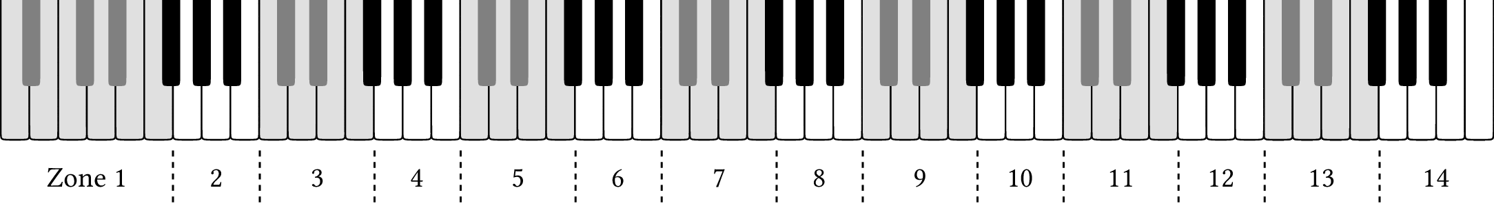
| PDF | PNG | 15.13 | Keyboard zones
|
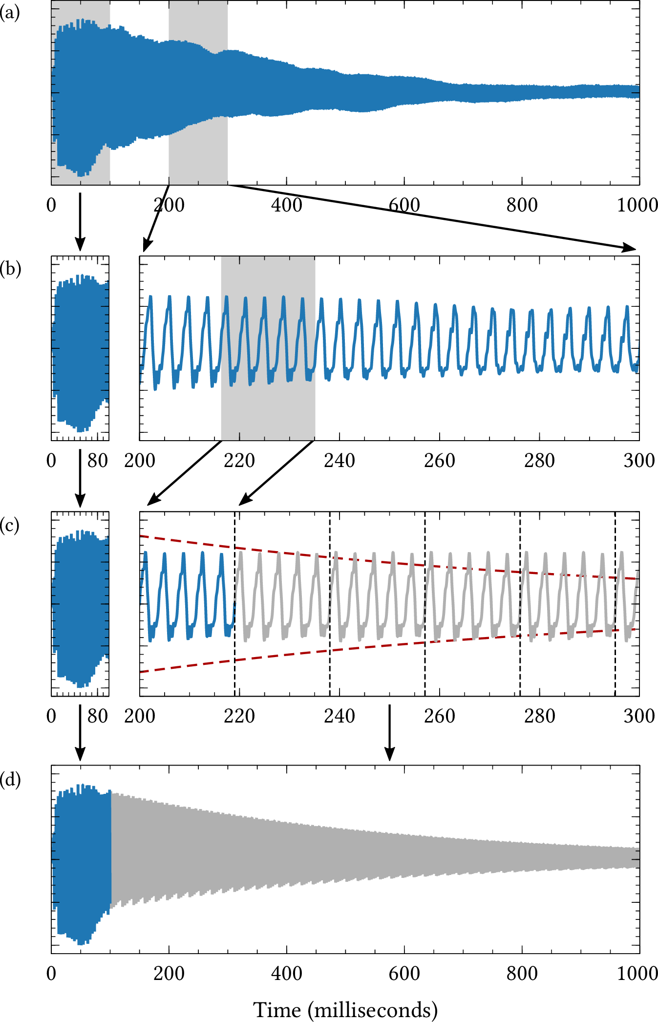
| PDF | PNG | 15.14 | Transient and loop
|
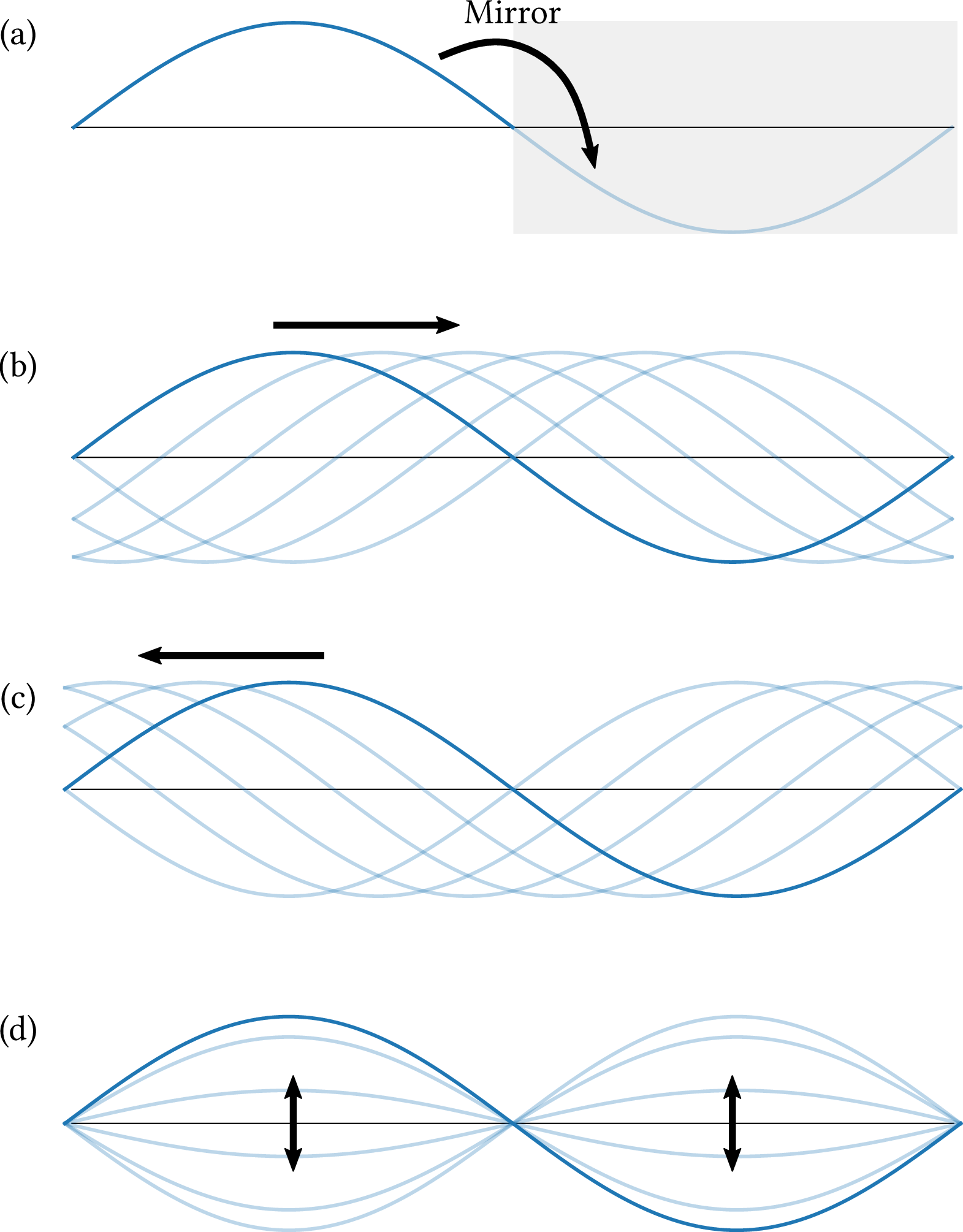
| PDF | PNG | 15.15 | D'Alembert's solution
|
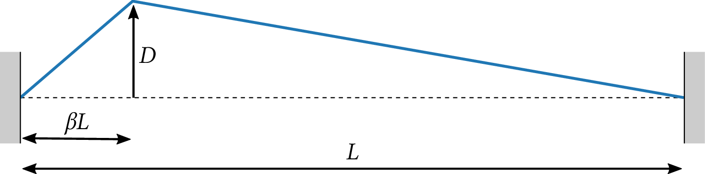
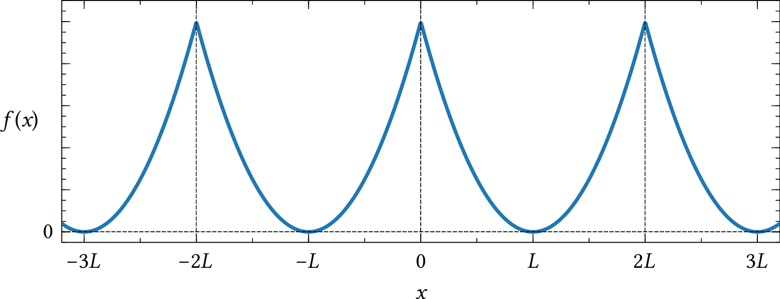
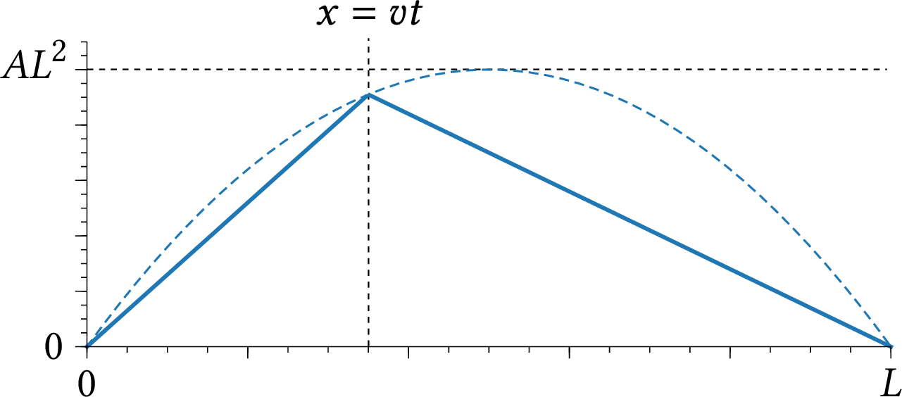
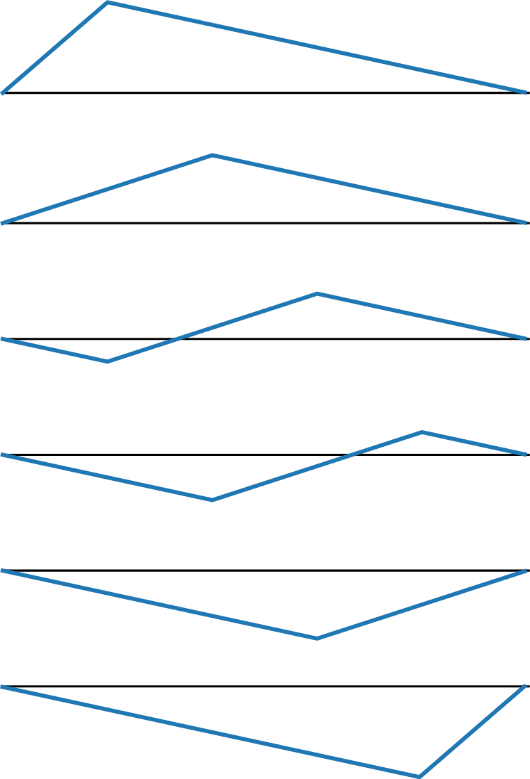
| PDF | PNG | 15.16 | Motion of a plucked string
|
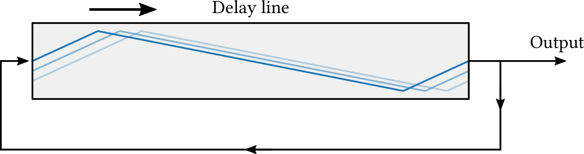
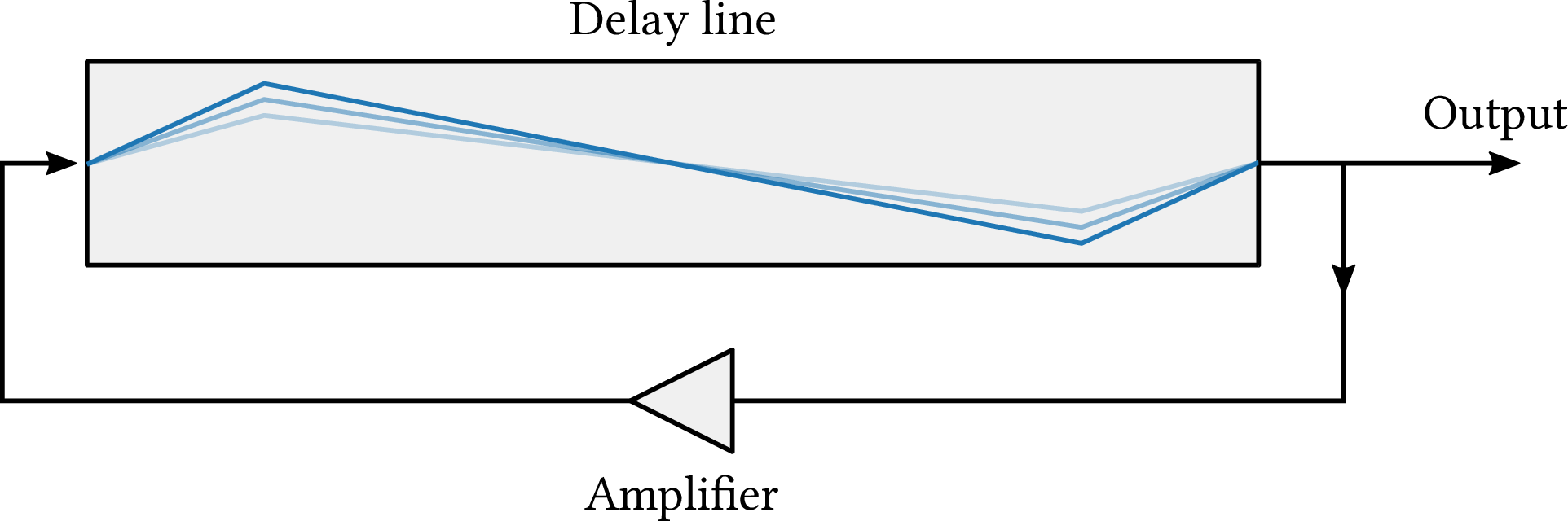
| PDF | PNG | 15.17 | Delay line with feedback
|
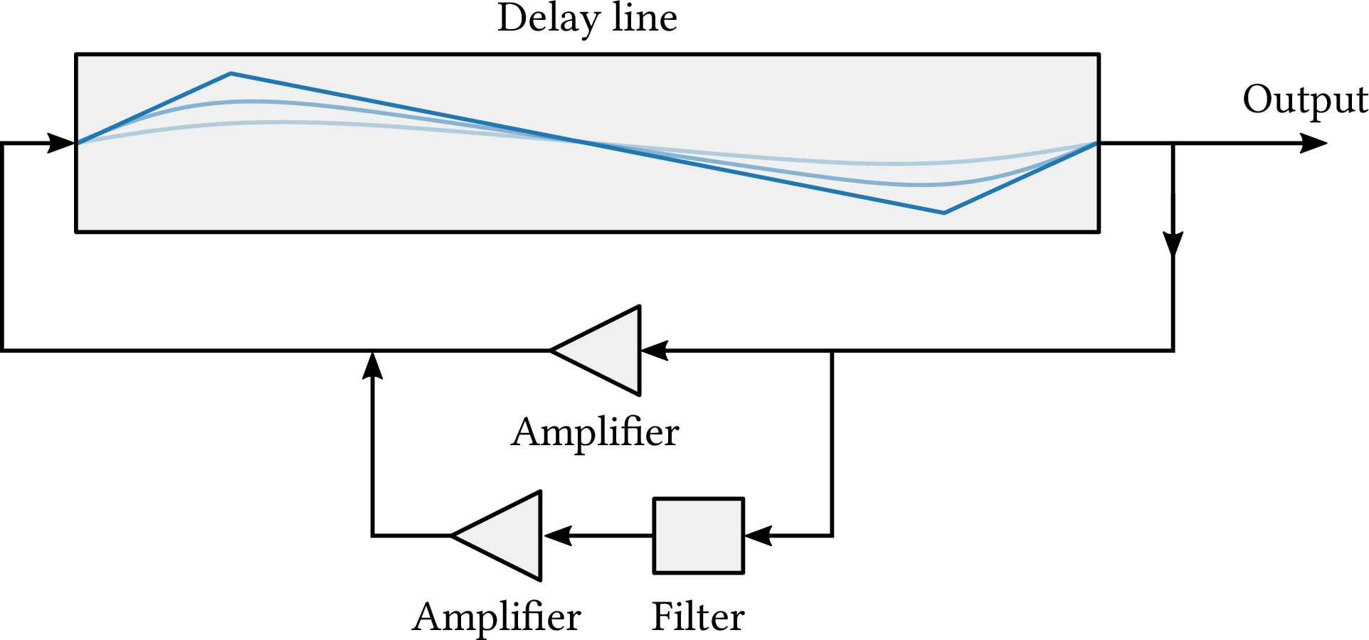
| PDF | PNG | 15.18 | Feedback and attenuation
|
| PDF | PNG | 15.19 | Karplus-Strong algorithm
|